
Lab 5 - Molecular Geometry
Purpose
-
ATo explore some simple molecular structures.
-
BTo explore the relationship between bond order and bond length.
-
CTo explore resonance structures.
Goals
-
1To compare Lewis structures to three-dimensional models.
-
2To visualize the three-dimensional structures of some common molecules.
-
3To obtain bond angle, bond length, and hybridization data for molecules.
-
4To rationalize differences in predicted and measured values.
-
5To learn how to use molecular modeling software.
Introduction
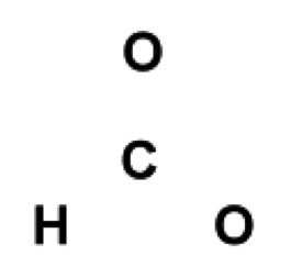
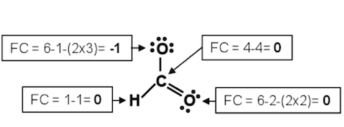
The chemical and physical properties of covalently bonded materials are related to the spatial arrangement of the atoms and other electrons not involved in the actual bond formation. There are many ways to depict the spatial arrangement in both two and three dimensions. A Lewis structure is a two-dimensional representation of the arrangement of the atoms, bonding electrons and non-bonding (lone pair) electrons in a covalent material. In a Lewis structure, the nucleus is represented by the atomic symbol with a line between the atoms in a bond depicting each pair of shared bonding electrons in the structure. Non-bonding electrons around the atoms are depicted as dots The steps to building a Lewis structure representation of a molecule are shown below. The Lewis structure of the formate ion, CHO2-, will be used as an example.-
1Calculate the electrons required (ER) = the minimum number of electrons necessary to satisfy the octet rule for the non-hydrogen atoms and the duet rule for hydrogen. For CHO2-, this would be (2 electrons x 1 hydrogen atom) + (8 electrons x 3 non-hydrogen atoms) = 2 + 24 = 26 electrons required.
-
2Calculate the number of available valence electrons (VE) = the total number of electrons available for the molecule. For example, in CHO2-, this would be (1 C atom x 4 electrons) + (1 H atom x 1 electron) + (2 O atoms x 6 electrons) + (1 electron as the ion has a charge of -1) = 4 + 1 + 12 + 1 = 18 valence electrons. NOTE: For ions, the charge must be factored into this calculation by adding the charge on an anion or subtracting the charge on a cation.
-
3Calculate the Shared Pairs (SP) = the number of electrons to be shared in bonds. The SP is 1/2 (ER-VE); for CHO2-, this would be 1/2 (26 - 18) = 4 shared pairs or four bonds.
-
4Calculate the Lone Pairs (LP) = the number of electron pairs belonging to only one atom. The LP is 1/2 (VE-(2xSP)); for CHO2-, this would be 1/2(18 - (2x4)) = 5 lone pairs. Notice that VE = 2 x (SP + LP).
-
5Place the first atom in the molecular formula as the central atom, surrounded by the other atoms in the compound.
-
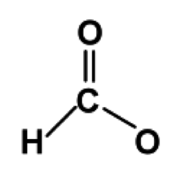
6Draw bonds (shared pairs) from the central atom to each surrounding atom. The bonds are represented as lines; each line represents two electrons. The number of lines should be equal to the number of shared pairs calculated in step 3, which in this case is four. Since hydrogen follows the duet rule, it prefers only one bond. The fourth bond can be drawn to either one of the oxygen atoms.
-
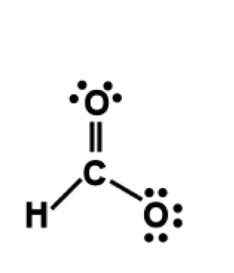
7Draw lone pairs on each of the non-hydrogen atoms. A lone pair is represented as two dots; each dot represents an electron. Each non-hydrogen atom prefers eight electrons in the vicinity of the atom. If an atom has 1 bond, it requires 3 lone pairs. If an atom has 2 bonds, it requires 2 lone pairs. If an atom has 3 bonds, it requires 1 lone pair. If an atom has 4 bonds, do not add any additional lone pairs. In our example, C requires no lone pairs, one oxygen requires 3 lone pairs and one oxygen requires 2 lone pairs.
8
Calculate the formal charge (FC) on each atom. For an atom:
( 1 )
FC = VE - SP - (2 x LP)
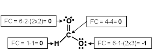 The structure shown above is the Lewis structure representation of the formate ion.
Note that the structure could also have been draw with two bonds directed towards the
oxygen on the right. This is known as a resonance structure. Resonance structures
have the same number of electrons, but may have a different number of shared pairs or
the atoms in the structure may have different formal charges.
The structure shown above is the Lewis structure representation of the formate ion.
Note that the structure could also have been draw with two bonds directed towards the
oxygen on the right. This is known as a resonance structure. Resonance structures
have the same number of electrons, but may have a different number of shared pairs or
the atoms in the structure may have different formal charges.
 Once a Lewis structure has been drawn, one can evaluate the bond order of shared
pairs. A shared pair is a single bond with a bond order of 1; two shared pairs in a bond
is a double bond (bond order = 2) and three shared pairs in a bond is a triple bond (bond
order = 3). In general, the bond strength increases and bond length decreases as the
bond order increases. (The bond length is the distance between the centers of the two
atoms bonded together). Thus, a single bond is longer than a triple bond, but the triple
bond is stronger. NOTE: This general statement applies when comparing the bond order
of similarly bonded atoms.
However, as noted, the Lewis structure is a two-dimensional representation of the
molecule or ion. The two-dimensional diagram does not show us the geometry or shape
of the molecule in three-dimensional space. Over the years, many theories have attempted to explain the shape of
covalently bonded substances; one of the simplest is the Valence Shell Electron Pair
Repulsion (VSEPR) theory. In most molecules, electrons occur in pairs, either as part of
a bond (bonding pair) or as a lone pair; these pairs occupy space around an atom. The
theory proposes that these areas or electron regions repel one another. VSEPR theory's
main postulate is that the regions around a given atom will arrange themselves to
minimize this repulsion by positioning themselves as far apart as possible. This leads to
a predictable shape based on simple geometry.
For the purposes of the VSEPR theory, it is more helpful to think about electron groups
(rather than just electron pairs) and the regions the groups occupy in space. A lone pair
or bonding pair are each considered to be an electron group. However, the four
electrons in a double bond or the six electrons in a triple bond are also considered to be
one electron group. In each case they occupy one region where they are bonding two
atoms together.
The position of the electron groups determines the angles at which centers of those
electron regions are located. As a result, the angle between atoms that may be at the ends of those electron groups is also determined. These angles for covalent compounds
that obey the octet rule are shown in the table below. The values in the table give the
angles between the centers of the electron regions. If these are bonding groups (single,
double or triple bonds), this number also is the bond angle.
Once a Lewis structure has been drawn, one can evaluate the bond order of shared
pairs. A shared pair is a single bond with a bond order of 1; two shared pairs in a bond
is a double bond (bond order = 2) and three shared pairs in a bond is a triple bond (bond
order = 3). In general, the bond strength increases and bond length decreases as the
bond order increases. (The bond length is the distance between the centers of the two
atoms bonded together). Thus, a single bond is longer than a triple bond, but the triple
bond is stronger. NOTE: This general statement applies when comparing the bond order
of similarly bonded atoms.
However, as noted, the Lewis structure is a two-dimensional representation of the
molecule or ion. The two-dimensional diagram does not show us the geometry or shape
of the molecule in three-dimensional space. Over the years, many theories have attempted to explain the shape of
covalently bonded substances; one of the simplest is the Valence Shell Electron Pair
Repulsion (VSEPR) theory. In most molecules, electrons occur in pairs, either as part of
a bond (bonding pair) or as a lone pair; these pairs occupy space around an atom. The
theory proposes that these areas or electron regions repel one another. VSEPR theory's
main postulate is that the regions around a given atom will arrange themselves to
minimize this repulsion by positioning themselves as far apart as possible. This leads to
a predictable shape based on simple geometry.
For the purposes of the VSEPR theory, it is more helpful to think about electron groups
(rather than just electron pairs) and the regions the groups occupy in space. A lone pair
or bonding pair are each considered to be an electron group. However, the four
electrons in a double bond or the six electrons in a triple bond are also considered to be
one electron group. In each case they occupy one region where they are bonding two
atoms together.
The position of the electron groups determines the angles at which centers of those
electron regions are located. As a result, the angle between atoms that may be at the ends of those electron groups is also determined. These angles for covalent compounds
that obey the octet rule are shown in the table below. The values in the table give the
angles between the centers of the electron regions. If these are bonding groups (single,
double or triple bonds), this number also is the bond angle.
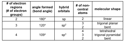 Also shown in the above table are the hybridized orbitals used to form the σ-bonds (sigma bonds) and to hold the lone pairs. Chemists invoke hybrid orbitals based on the
assumption that one atom will point its electron region directly at an atom to which it
bonds. s orbitals do not point in any direction, and simple p atomic orbitals lie 90o apart
along the x, y and z-axes. Regions in space that point 109°, 120° or 180° apart result by taking mathematical combinations (hybrids) of the simple atomic orbitals. Hybrid orbitals
have thus been incorporated into the language that describes covalent bonding.
When we use the term molecular geometry or molecular shape, we are not describing
the shape of the electron regions, but rather, the location of the atoms. The words used
to describe the shapes are therefore describing the location of the atoms. Where four
atoms surround a central atom, the shape would be tetrahedral. Where three atoms
surround a central atom, the shape would either be trigonal planar or pyramidal.
Where two atoms surround a central atom, the shape would either be linear or bent.
It is difficult to represent three-dimensional structures, like molecules, on a flat piece of
paper. It is equally as difficult to look at a molecular structure drawn on a piece of paper
and imagine what it would look like in three-dimensions. With the help of a molecular
model kit and a computer modeling program, you will be able to visualize a molecule in
three-dimensions. In this lab, you will use a computer program within WebAssign that
allows molecules to be rotated, just like you could manually rotate a model built with a
model kit. You will also be able to use the computer program to obtain experimentally
determined measurements, such as bond angles and bond lengths, for the molecule
under investigation.
In introductory chemistry courses, we often predict bond angles and bond lengths in
simple molecules based on VSEPR or hybridization. However, our predictions are simply
approximations because other factors influence the structure of real molecules. In this
lab, you will compare the bond angles and bond lengths predicted from theory to the
experimentally determined values. You will then be asked to explain differences that
occur between the experimental values and the theoretical values.
Also shown in the above table are the hybridized orbitals used to form the σ-bonds (sigma bonds) and to hold the lone pairs. Chemists invoke hybrid orbitals based on the
assumption that one atom will point its electron region directly at an atom to which it
bonds. s orbitals do not point in any direction, and simple p atomic orbitals lie 90o apart
along the x, y and z-axes. Regions in space that point 109°, 120° or 180° apart result by taking mathematical combinations (hybrids) of the simple atomic orbitals. Hybrid orbitals
have thus been incorporated into the language that describes covalent bonding.
When we use the term molecular geometry or molecular shape, we are not describing
the shape of the electron regions, but rather, the location of the atoms. The words used
to describe the shapes are therefore describing the location of the atoms. Where four
atoms surround a central atom, the shape would be tetrahedral. Where three atoms
surround a central atom, the shape would either be trigonal planar or pyramidal.
Where two atoms surround a central atom, the shape would either be linear or bent.
It is difficult to represent three-dimensional structures, like molecules, on a flat piece of
paper. It is equally as difficult to look at a molecular structure drawn on a piece of paper
and imagine what it would look like in three-dimensions. With the help of a molecular
model kit and a computer modeling program, you will be able to visualize a molecule in
three-dimensions. In this lab, you will use a computer program within WebAssign that
allows molecules to be rotated, just like you could manually rotate a model built with a
model kit. You will also be able to use the computer program to obtain experimentally
determined measurements, such as bond angles and bond lengths, for the molecule
under investigation.
In introductory chemistry courses, we often predict bond angles and bond lengths in
simple molecules based on VSEPR or hybridization. However, our predictions are simply
approximations because other factors influence the structure of real molecules. In this
lab, you will compare the bond angles and bond lengths predicted from theory to the
experimentally determined values. You will then be asked to explain differences that
occur between the experimental values and the theoretical values.
Equipment
-
1Chem-Tutor model kit
-
1computer with internet browser
-
1Molecular Geometry In-Lab assignment in WebAssign
About the model kit
The Chem-Tutor model kit was designed by Professor Samuel G. Levine for use by his organic chemistry students at North Carolina State University. Atoms: Atoms are represented by jacks that have one, two, three or four pegs coming out. Each peg represents an electron region (or electron group). The electron regions (groups) can be single bonds, double bonds, triple bonds or lone pairs. In general, black jacks are used for carbon, blue for nitrogen, red for oxygen, white for hydrogen and yellow for sulfur. More important than color is the number of pegs. The type of atom/jack to use is determined by the Lewis structure of the molecule. Bonds: Green bonds can be used for single, double or triple bonds. Do not bend the green bonds to force a molecule into a particular shape. Although you are strong enough to bend these bonds, it takes energy for atoms and molecules to bend away from the predicted angles and shapes. The molecules prefer to exist in the lowest energy configurations ("straight" green bonds). Black bonds between two carbon atoms can be used for carbon-carbon double bonds. You will notice that the pegs on each carbon define a plane, and that the two carbons are coplanar. The atoms at the ends of the bond are fixed in place. DO NOT attempt to twist this bond. White bonds are made out of rubberized plastic, and are the only ones that are meant to bend. They are only used for special "strained" structures that you will not encounter in this lab.About the computer modeling software
The molecules in your WebAssign In-Lab are viewed with jmol, a javascript plug-in. The computer files viewed with jmol contain real data from measurements on these molecules. Often we find that molecules follow what is predicted from textbooks. Occasionally, they do not. Do not be surprised if what you observe is sometimes different than what you might predict! Rotating a molecule: A molecule in the viewing area can be rotated in all directions. This can be achieved by holding down the left mouse button while moving the mouse. After a few tries at this, you should be able to manipulate the molecule any way that you want. To determine a bond length: Double click on one of atoms in the bond. The cursor will change to a "+". Then double click on the other atom in the bond. The measurement will be displayed in nanometers (nm). To make the measurement disappear, re-measure the bond in the same way. To determine a bond angle: Double click on one of the atoms of the angle. The cursor will change to a "+". Then single click on the vertex of the angle. And last, double click on the on the third atom in the angle. The measurement will be displayed in degrees. To make the measurement disappear, re-measure the angle in the same way.Reagents
No chemicals will be used in this experiment.Safety
None of the materials being used in this experiment present a safety hazard. However, the work is being done in a laboratory and the usual rules about eye protection and proper clothing apply. Gloves will not be provided for this experiment as no chemicals are involved.Waste Disposal
Since no chemicals are being used in this experiment, there will not be any waste for disposal.Prior to Class
Please complete WebAssign prelab assignment. Check your WebAssign Account for due dates. Students who do not complete the WebAssign prelab are required to bring and hand in the prelab worksheet.
Lab Procedure
You will notice the format of this lab experiment is different than other experiments. You will build a series of models and investigate them on the computer. Questions to help you with your observations are intermingled with the procedure. Please answer the questions in your lab manual along with any other observations you make while you are building the structures.- Launch a web browser.
- Open one partner's Molecular Geometry In-Lab in WebAssign.
Part A: Exploring Simple Structures
For each of the following molecules,-
•Review the correct, complete Lewis structure(s), including any resonance structures and any formal charges that you drew in your Prelab assignment.
-
•Build the molecule with the model set.
-
•Look at the molecule in your In-Lab assignment on WebAssign.
-
•Fill in the table and answer the questions below.
Data Table A: Exploring Simple Structures
Question A1: For each of the six molecules, how did your Lewis structures compare to
the molecular models and the models on the computer? Were they the
same or different? Explain.
Question A2: For each of the six molecules, was your Lewis structure a good and
accurate representation of the molecule's actual shape? Explain why or
why not.
Question A3: Did the model set and computer models help you identify the molecular
shape better than the Lewis structures? Do you think models are helpful
with 3D visualization?
Question A4: Did you have any other interesting observations? Please elaborate.
Part B: Bond Order vs Bond Length
For each of the following molecules,-
•Review the correct, complete Lewis structure(s), including any resonance structures and any formal charges that you drew in your Prelab assignment.
-
•Build the molecule with the model set.
-
•Look at the molecule in your In-Lab assignment on WebAssign.
-
•Fill in the table and answer the questions below.
Data Table B: Bond Order vs Bond Length
Question B1: What conclusions can you draw about bond order and bond length?
Question B2: Looking back at your data in Part A, are all single bonds the same length?
Based on these observations, can you make a generalization about the
length of all single bonds compared to double bonds or all double bonds
compared to triple bonds? What general rule can you make?
Question B3: Did you have any other interesting observations? Please elaborate.
Part C: Resonance Structures
Draw the Lewis structures for Part C on your lab worksheet. For each of the following molecules,-
•Review the correct, complete Lewis structure(s), including any resonance structures and any formal charges that you drew in your Prelab assignment.
-
•Build the molecule with the model set.
-
•Look at the molecule in your In-Lab assignment on WebAssign.
-
•Fill in the table and answer the questions below.
Data Table C: Resonance Structures
Question C1: Which of the three molecules had resonance structures that were equal?
Which did not? Explain.
Question C2: How can you confirm that the resonance structures are equal for a
molecule? Explain.
Question C3: If there was a molecule with unequal resonance structures, which
structure is the best according to the computer modeling? Can you tell
which structure the computer is displaying? How? Do your observations
agree with what you have learned about formal charge?
Question C4: Did you have any other interesting observations? Please elaborate.
-
•When you are done, clean up any model set structures and leave the sets as you found them when you arrived in the lab.
-
•Before leaving, go to a computer in the laboratory and enter your results in the InLab assignment. If all results are scored as correct, log out. If not all results are correct, try to find the error or consult with your teaching assistant. When all results are correct, note them and log out of WebAssign. The InLab assignment must be completed by the end of the lab period. If additional time is required, please consult with your teaching assistant.