
Lab 7 - Rotational Inertia
Introduction
When you were younger, you might have had toy cars that you rubbed quickly across the floor several times to "rev them up." Then, when you put them down, they would go zipping along for some distance. Or perhaps you have seen an auto accident on television where the wheels of the overturned car continued to turn for a little while. Maybe you have watched a helicopter land, and have noticed that the blades continue to rotate after the pilot turns the engine off. All of these are examples of rotational inertia. The toy car has a little wheel inside, called a flywheel, which is attached to the car's wheels. When you "rev it up" the flywheel begins to spin. Then, when you let the car go, the flywheel continues to spin because of rotational inertia, and so turns the wheels. The wheels on the overturned car and the helicopter blades both continue to turn until friction overcomes their rotational inertia. You have already learned about inertia in linear systems; an object in motion will continue in motion as long as there is no net force acting on it. Rotational inertia is a similar concept applied to objects whose motion is rotational instead of linear. The rotational inertia of an object is that object's resistance to a change in its angular velocity. That is, if an object is spinning, it has a tendency to keep spinning until a net torque acts upon it. This is just another manifestation of Newton's second law.Discussion of Principles
In Newton's second law,F = ma
the mass m of an object is a measure of its inertia. Clearly the smaller the mass, the less force is required to change the object's linear velocity. In rotational motion, it is the rotational inertia, often called the moment of inertia I that determines the torque τ,
required to change an object's angular velocity ω.
The analogue of Newton's second law for rotational motion is
( 1 )
τ net = I α
net = I α τnet
is the net torque and net α
is the angular acceleration. The moment of inertia of an object depends on the shape of the object and the distribution of its mass relative to the object's axis of rotation. A uniform disk of mass m is not as hard to set into rotational motion as a "dumbbell" with the same mass and radius. For a symmetric, continuous body (like a solid disk) that is rotating about an axis of symmetry, e.g., an axle through the center and perpendicular to the disk, the moment of inertia is calculated by carrying out the integral
( 2 )
I =
| r2dm | |
 | |
dm
is the tiny bit of mass located a distance r from the axis of rotation. For a collection of n point masses, the moment of inertia is calculated by carrying out the sum
( 3 )
I =
| n | mi ri2 |
 | |
| i=1 |
mi
and ri
are the mass and position, respectively of the ith particle. Thus, for the dumbbell n = 2
and with mass m at each end, seperated by a distance d, the moment of inertia is
( 4 )
I = 2m
= m
 |
| d |
| 2 |
 | 2 |
| d2 |
| 2 |
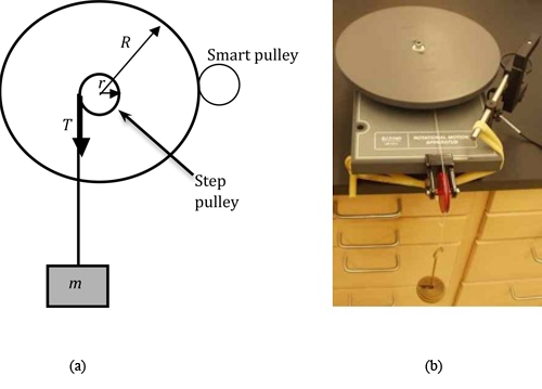
Figure 1: Sketch and photo of the apparatus
τf
and that of the tension τtension.
The magnitude of the torque due to the tension is
( 5 )
τ = rT
( 6 )
τnet = rT − τf
τnet = I α
we obtain
net = I α ( 7 )
rT − τf = Iα
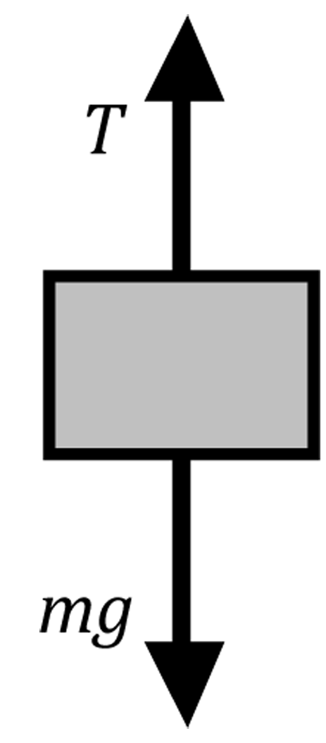
Figure 2: Free body diagram for the hanging mass
( 8 )
mg − T = ma
( 9 )
T = m(g − a)
a'
is the tangential acceleration of a point at the edge of the wheel. This is where we will actually measure the acceleration with the Smart Pulley. The angular acceleration of the wheel is related to these tangential accelerations by
( 10 )
α =
=
| a |
| r |
| a' |
| R |
T = m(g − a)
and (10)α =
=
| a |
| r |
| a' |
| R |
rT − τf = Iα
as
( 11 )
m(g − a)r − τf = I
 |
| a |
| r |
 |
Analysis by Linearization
There are two points to consider with regard to Eq. (11) m(g − a)r − τf = I
|
| a |
| r |
|
τf.
In this analysis, we will make an approximation that will result in Eq. (11) m(g − a)r − τf = I
|
| a |
| r |
|
g >> a,
and, therefore T ≈ mg.
As a consequence, Eq. (11) m(g − a)r − τf = I
|
| a |
| r |
|
( 12 )
mgr − τf = I
|
| a |
| r |
|
mgr − τf = I
|
| a |
| r |
|
( 13 )
a =
m +
|
| gr2 |
| I |
|
|
| −τf r |
| I |
|
gr2 / I
and the y-intercept will be τrf / I.
Note: If we determined the accelerations, a1
and a2,
for only two masses m1
and m2,
then
( 14 )
slope =
=
| a2 − a1 |
| m2 − m1 |
| gr2 |
| I |
( 15 )
I =
| (m2 − m1)gr2 |
| (a2 − a1) |
Analysis by the Exact Method
As in the note above, suppose the procedure is repeated with two different masses,m1
and m2,
resulting in accelerations a1
and a2,
respectively.
( 16 )
m1 (g − a1)r − τf = I
|
| a1 |
| r |
|
( 17 )
m2 (g − a2)r − τf = I
|
| a2 |
| r |
|
τf
can be mathematically eliminated. Solving the two simultaneous Eqs. (16) m1 (g − a1)r − τf = I
|
| a1 |
| r |
|
m2 (g − a2)r − τf = I
|
| a2 |
| r |
|
( 18 )
I =
| (m2 − m1)gr2 + (m1a1 − m2a2)r2 |
| (a2 − a1) |
I =
and (18)| (m2 − m1)gr2 |
| (a2 − a1) |
I =
.
| (m2 − m1)gr2 + (m1a1 − m2a2)r2 |
| (a2 − a1) |
Objective
In this experiment you will use a wheel with a step pulley to measure the acceleration of the rotating wheel and determine the moment of inertia of the wheel. You will also determine the moment of inertia of an extension that you will add to the wheel.Equipment
- Wheel with step pulley
- Smart Pulley with photogate
- String
- Mass with hanger
- DataStudio software
- Caliper
- Balance
- Meter stick
- Hoop
- Plate
Procedure

a'
at the rim of the wheel. From this, you will calculate the tangential acceleration at the step pulley's rim using Eq. (10)α =
=
| a |
| r |
| a' |
| R |
( 19 )
Itotal = Iwheel + Iextension.
1
Weigh the wheel and record this value on the worksheet. You do not need to include the hanger.
2
Use a meter stick to measure the diameter of the wheel. Once you have found the diameter, use it to find the radius R of the wheel, and record this value on the worksheet.
3
Calculate the accepted value for the Moment of Inertia for your wheel using
( 20 )
Idisk = (1/2)MR2.
4
Use a caliper to measure the diameter of your step pulley. This is the smallest pulley that the string is wrapped around. See Appendix D.
Use the diameter to calculate the radius r of your step pulley, and record this value on the worksheet.
5
Open the DataStudio file associated with this lab. A screen similar to Fig. 3 is displayed.
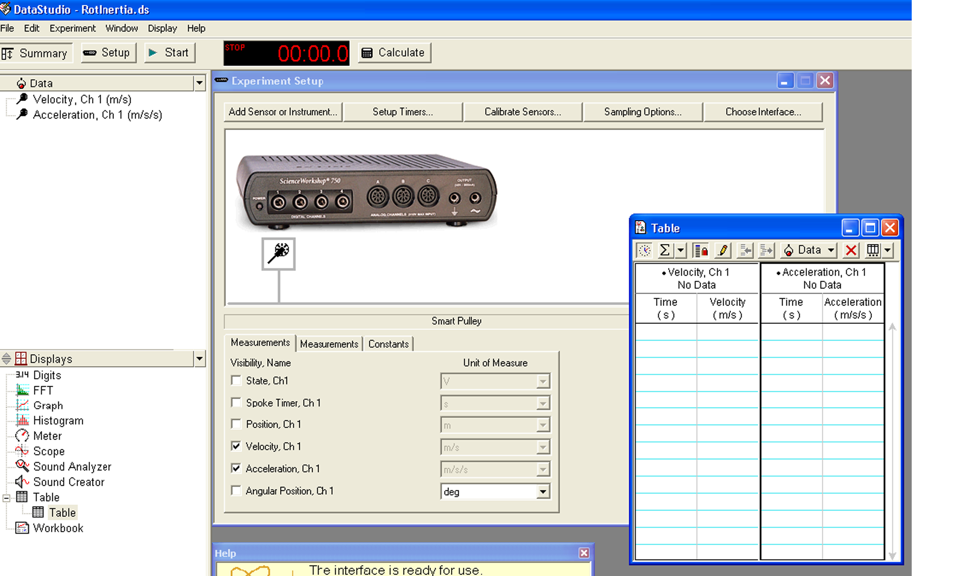
Figure 3: Start-up screen for rotational inertia lab
6
Use the balance to determine the mass m1
of the hanger and record this value on the worksheet. This will be the mass for the first data point.
7
Wind the string onto the smallest diameter step pulley.
Then pass the string over the second pulley and attach the hanger to the end of the string so that it hangs over the edge of the table.
8
Click the Start button once and allow the wheel to start rotating. Click Stop after the mass hits the floor or when you run out of string and the wheel begins to turn the opposite way.
It is not necessary that you try to release the wheel and click the mouse at exactly the same time, you might want to click the mouse about half a second before you release the wheel.
Be sure to stop the wheel from rotating when it runs out of string.
The table of times, velocities, and accelerations like the one shown in Fig. 4 is automatically completed.
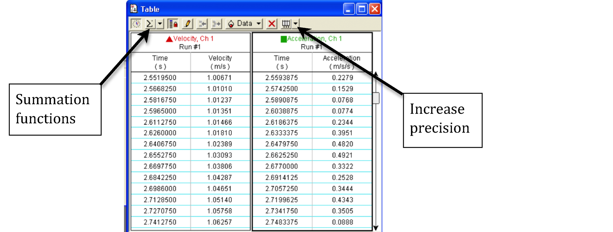
Figure 4: Data table for a sample run
9
Scroll through the data to choose ten successive accelerations near the middle of the run, not those at the very beginning or the very end.
Record these ten values in the data table on the worksheet.
10
Using the summation function located in the top left corner of the data table window, determine the average of these ten acceleration measurements and enter the result on the worksheet.
You might need to repeat the run if the numbers are very erratic.
11
Repeat steps 7 through 9 three more times by adding mass to the hanger in increments of 50 grams.
Note: You might need to increase the precision for the accelerations as you add more runs of data. You can do this by clicking on Increase Precision in the menu at the top right hand corner of the data table window. See Fig. 4.
Checkpoint 1:
Ask your TA to check your data and calculations before proceeding.
Ask your TA to check your data and calculations before proceeding.
Procedure A: Linearization Method
12
Using Excel, create a graph of acceleration vs. hanging mass. See Appendix G.
13
Using the Linest function, determine the slope and intercept. Record these values on the worksheet. See Appendix J.
14
From the slope and intercept values calculate the moment of inertia and frictional torque using Eq. (13) a =
m +
|
| gr2 |
| I |
|
|
| −τf r |
| I |
|
15
Calculate the percent difference between the moment of inertia that you just calculated and the moment of inertia you calculated in step 3. See Appendix B.
Checkpoint 2:
Ask your TA to check your data and calculations before proceeding.
Ask your TA to check your data and calculations before proceeding.
Procedure B: Exact Method
16
Use the data from the first and last trial to calculate the moment of inertia using Eq. (18)I =
.
| (m2 − m1)gr2 + (m1a1 − m2a2)r2 |
| (a2 − a1) |
17
Calculate τf using Eq. (17) m2 (g − a2)r − τf = I
|
| a2 |
| r |
|
18
Calculate the percent difference between the moment of inertia that you just calculated and the moment of inertia you calculated in step 3.
Checkpoint 3:
Ask your TA to check your calculations before proceeding.
Ask your TA to check your calculations before proceeding.
Procedure C: Determining the Moment of Inertia of the Extension
19
Choose either the hoop or the plate as the extension to add to the wheel.
Measure the dimensions and the mass of the extension and record these values on the worksheet.
20
Calculate the accepted value of the moment of inertia for the extension (use the formulas provided on the worksheet).
21
Algebraically solve Eq. (11) m(g − a)r − τf = I
|
| a |
| r |
|
22
Mount the extension on the wheel and perform steps 7 through 9 with a hanging mass of 200 g.
23
Find the acceleration a'
of the wheel, and the acceleration a of the step pulley. Record these values on the worksheet.
24
Using the frictional torque τf determined from step 17, and the formula from step 21, calculate the total moment of inertia of the extension and the wheel. Record this value on the worsheet.
25
Using the moment of inertia of the wheel obtained by the exact method from step 16, and Eq. (19) Itotal = Iwheel + Iextension.
find the moment of inertia of the extension, by itself. Record this value on the worksheet.
26
Find the percent difference between this value and the accepted value you calculated in step 20. Record this value on the worksheet.
Checkpoint 4:
Ask your TA to check your calculations.
Ask your TA to check your calculations.