
Torques and Static Equilibrium
Introduction
The primary purpose of this lab is to introduce you to the quantity called the torque or, as engineers call it, the moment of a force and show how this quantity behaves in a system in static equilibrium. Torque is a measure of the ability of an applied force to cause an object to turn and is the rotational analogue to force. As we know, a net force applied to an object will result in the object undergoing an acceleration. If we apply a torque to a rigid body, this will result in an increase or decrease in its rotation rate. The symbol that we use to signify torque is τ and is the vector cross product of the applied force and the distance from the pivot point to the point on the rigid body where the force is applied. When the force is oriented perpendicular to the axis formed by the pivot point and the point at which the force is applied, this becomes where rperpendicular is sometimes called the lever arm. Torque is measured in units of N · m.
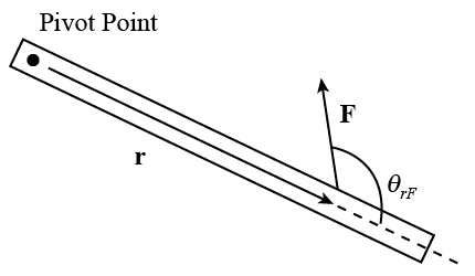
Figure 1
Definition of Static Equilibrium
For the general motion of a rigid body subject to a torque, we know that such torques will give rise to an angular acceleration, α, such that where I is the moment of intertia of the system and αis its angular acceleration. Likewise for the general motion of the same system subject to a force, F, we know that In general for a system that is in static equilibrium, this is defined as the state for which the system is undergoing neither a rotational or a linear acceleration. Hence we find that when an object is said to be in static equilibrium.Objectives
The objectives of this experiment are to:-
1learn to measure torque due to a force and to adjust the magnitude of one or more forces and their lever arms to produce static equilibrium in a meterstick balanced on a knife-edge;
-
2use the conditions for equilibrium to determine the mass of the meterstick and the mass of an unknown object.
Apparatus
- Meterstick
- Pivot hanger
- Mass hangers
- Set of masses
- Pulley on a stand
- String and small beaker
- Container of washers
- Triple beam balance
Procedure
Please print the worksheet for this lab. You will need this sheet to record your data.
The Apparatus
You will have a meterstick which has a hanger on it so that it can be balanced on a stand. This hanger will be referred to as the pivot hanger. The hanger has a knife edge and the stand has a groove into which the knife edge fits. There are additional hangers, that can be placed at any points on the meterstick, on which you can hang various masses. The force being exerted on the meterstick by a hanging mass, m1, has magnitude, m1g. (For more details on this, please see your lecture notes or consult your text.)Before We Begin
Slide the pivot hanger to the 50 centimeter mark and place the knife edge on the grooves on the stand. (You should attach the hangers with the adjustment screw on the bottom. Although this is somewhat inconvenient, the system works much better this way.) If the meterstick does not remain horizontal, move the hanger slightly until it does. Moving the hanger one way will make the imbalance worse, while the other way makes it better. Note the hanger's location when the stick remains at rest. Since the forces on the stick must add to zero and the stand can only exert a force on the knife edge, it follows that the effect of gravity on the meterstick is a single force, acting down at the point on the meterstick above the knife edge. This does not determine the magnitude of the force of gravity, just its location. The location is called the center of gravity. The mass of the meterstick will be determined later.
Note: All positions recorded in this lab are relative to the scale imprinted on the meterstick.
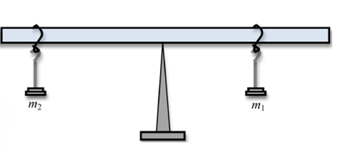
Figure 2
Part 1: Static Equilibrium
1
Leave the hanger at the center of gravity of the meterstick, so that it can pivot on the stand about that point. Put two more hangers on the meterstick, one on each side of the pivot. Hang different weights on these two hangers and slide them around until positions are located such that the meterstick remains horizontal, at rest. Write down the sizes and positions of the two hanging masses. Also weigh a hanger to determine and record its mass.
2
Repeat this procedure two more times with different sets of masses and again note their sizes and positions.
Analysis
3
For each of the sets of masses and positions you found above, you are to show that the condition for static equilibrium,
is in fact satisfied. Here the vector sign on the torque, τ,just means that if the torque tends to rotate clockwise about the pivot it is considered negative, while tending to rotate counterclockwise is positive. Since the force exerted by the stand and the force exerted by gravity act right at the pivot point, their corresponding torques about this point are zero. (Don't forget to include the torque due to the gravitational force on the hangers.)
Part 2: Finding the Mass of the Meterstick
1
You can use the condition for static equilibrium to determine the mass of the meterstick. Move the pivot hanger from the center of gravity and fasten it at the 40 cm mark. Now the meterstick is no longer in equilibrium. Now remove one of the other hangers and move the remaining one, with some known mass on it, until static equilibrium is obtained. (You may have to change the mass on the hanger to achieve this.)
2
The two torques about the pivot must cancel. Since distances to the pivot can be measured and the mass on the hanger is known, the mass of the meterstick can be determined (assuming it to have a uniform mass distribution).
3
Calculate the mass of the meterstick.
4
Now calculate the uncertainty associated with the mass that you have just determined based on the uncertainties in your measurements of each of the quantities contributing to your calculation.
5
Use the triple beam balance to measure the mass directly. What is the difference between the two values? Is this within the measurement error that you calculated?
Part 3: Determining an Unknown Mass
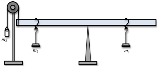
Figure 3
1
Position the center of gravity of the meterstick over the pivot hanger. Next, place a 50 gram mass, m1, on the hanger located at the 70.0 cm mark and a 80 gram mass, m2, on the hanger located at the 20.0 cm mark. Now loop the free end of the string tied to the bucket around the end of the meterstick at the 1.0 cm mark. Lastly, hang the bucket over the pulley as shown in the figures 3 and 4.
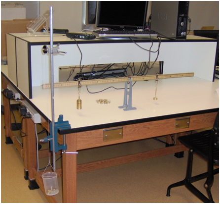
Figure 4
2
Under these conditions the meterstick will not be in equilibrium. Now add washers to the bucket until the meterstick is horizontal once again.
3
Calculate the sum of the torques about the pivot point due to m1 plus the hanger and m2 plus the hanger.
4
Now use the condition that Στ = 0
to find the mass of the bucket/washer system.
Error Analysis
5
Find the error on your mass calculation due to your measurement errors of the masses and their positions.
6
Measure the mass of the washer/bucket system using the balance.
7
Compare this measurement to your prediction above and its expected error.