Rotational Dynamics
Back to TopObjectives
-
•to explore the concept of moment of inertia
Equipment
data collection system, rotary motion sensor, mini rotational accessory, mass and hanger set, balance, super pulley with clamp, scissors, string, meter stick, stainless steel caliperIntroduction and Theory
Spinning and rotating objects are all around us. Bike tires, your car's drive shaft, and the Earth itself are all examples of spinning objects. How they spin, what makes them spin, and what factors will change the way they spin are all relevant questions answered by the physics of rotational dynamics. The only way to cause objects to spin is to apply an external torque, which is a force applied at some distance from the axis of rotation. The greater the applied torque, the greater the effect on the object's rate of spin. If a hanging mass on a string is attached to a pulley, the falling mass will create a torque.τnet = Fnet × r
I = MR2.
I =
ML2.
| 1 |
| 12 |
Relevant Equations
τnet = I · α
Procedure
Please print the worksheet for this lab. Answer all the questions on the Lab Worksheet prior to submitting the Inlab in WebAssign.Checkpoint:
Be sure to have your TA sign your lab worksheet, printed Inlab, and all printed graphs after each part is completed. Be sure the data can be seen on the graphs.
Be sure to have your TA sign your lab worksheet, printed Inlab, and all printed graphs after each part is completed. Be sure the data can be seen on the graphs.
Part 1: Varying Torque by Changing Force
1
Measure the mass of each sliding mass and the rotating arm, and then measure the length of the rotating arm. Record these values in the Inlab.
2
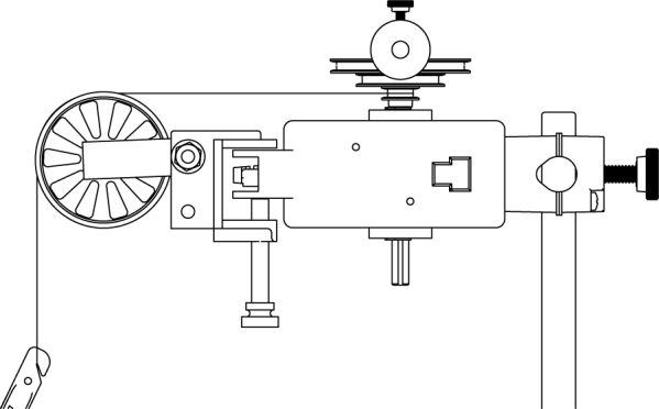
Attach one end of the string to the smallest pulley groove on the 3-step pulley and the other end to the mass hanger. Run the string from the 3-step pulley over the super pulley, allowing the mass hanger to hang freely.

Figure 2
Image: © and courtesy of PASCO scientific
3
Adjust the height of the super pulley so that the section of string between the top of the super pulley and the point at which it meets the 3-step pulley is horizontal.
4
Adjust the sliding masses along the rotating arm so the center of each mass is 15 cm from the axis of rotation.
5
Use the stainless steel caliper to measure the diameter of the three different pulley grooves on the 3-step pulley. Be sure to measure the part of the pulley that the string encircles, not the outside edge of the pulley. Record each value in Table 1 in the Inlab.
6
Add 25 g of mass to the 5-g mass hanger, giving a total of 30 g of mass hanging from the string.
7
Wind the string around the smallest pulley groove on the 3-step pulley until the mass hanger is just below the super pulley and hold it in place.
8
Begin data recording.
9
Release the hanging mass (from rest) and collect data until the rotating arm has completed 5 full revolutions. Use the "Linear Fit" tool to determine the average angular acceleration for each trial and then record the results in Table 2 in the Inlab.
10
For consistency, you may want to rename each data run with a definitive description of the setup used (example: "Data_Run_2_=_60_g").
11
Change the amount of mass (force) on the hanger: Repeat the previous steps two more times using an additional 30 g each time.
12
Record the 3 different masses used in Table 2 in the Inlab.
13
Calculate the torque produced by each hanging mass. Enter the values of torque in Table 2 in the Inlab.
14
Enter torque and acceleration into GA. Make a plot of torque vs. average angular acceleration. Report the slope of the graph and its uncertainty in the Inlab.
Part 2: Varying Rotational Inertia
1
Leave the string attached to the small pulley.
2
Move the sliding masses on the rotating arm so the center of each is 5 cm from the axis of rotation. Be sure to keep all other variables the same. Do not change the pulley diameter or the amount of mass attached to the string (60 g).
3
Calculate the moment of inertia. (Hint: Remember to find the moment of inertia of the entire rotating arm plus sliding masses. You need to double the moment of inertia added by the masses because there are two of them, as well as add the moment of inertia of the rod.) Enter the values of moment of inertia in Table 3 in the Inlab.
4
Calculate torque. (Hint: See equation 1τ = I · α
.) Enter the values of torque in Table 3 in the Inlab.
Wind the string around the middle pulley groove until the mass hanger is just below the super pulley and hold it in place.
5
Calculate the theoretical value of angular acceleration that will be produced by this torque. Enter the values of angular acceleration in Table 3 in the Inlab.
6
Repeat the collect data steps from Part 1. However, in this part you will keep the pulley diameter and mass constant and vary the rotational arm length.
7
Repeat the data collection procedure (above steps 3–5) one additional time with the center of each sliding mass 10 cm and 15 cm from the axis of rotation.
Record the hanging mass and pulley groove diameter in Part 2 of the Inlab.
8
Are the experimental and theoretical values of angular acceleration agreed within 10% for each of the trials?
9
State Newton's Second Law for rotational motion.
Note:
Remember to show all your calculations in the lab worksheet.
Remember to show all your calculations in the lab worksheet.

