
Lab 10 - Reflection and Refraction
Introduction
Geometric optics is one of the oldest branches of physics, dealing with the laws of refraction and reflection. The law of reflection was known to the ancient Greeks who made measurements that supported this law. The law of refraction, however, was not formulated mathematically until almost 1500 years later. Image formation by lenses and mirrors is explained by these two laws. Lenses and mirrors are the basic components of many common optical devices such as cameras, telescopes, eyeglasses, binoculars and microscopes. In geometric optics light is represented as rays coming from a light source. When these rays encounter a mirror, lens, or prism, for example, they bend or change direction. In this experiment, you will examine how light rays behave due to reflection and refraction in plane surfaces.Discussion of Principles
Reflection by a Plane Mirror
When light is incident on a surface, some of the light is reflected back while some of it is transmitted or absorbed. A plane mirror is a highly polished surface with minimal absorption or refraction of light. Nearly all of the light is reflected back. There are numerous rays coming from a single source. However, when analyzing the behavior of light using the ray model, we use just one, two, or three rays to show the path of the rays and image formation. These are known as ray diagrams. To understand reflection using the ray model, we need to first define certain terms. The incident ray is a ray from the light source incident on the plane mirror. The angle of incidenceθi
is the angle between the incident ray and the normal (perpendicular) at the point of incidence. The reflected ray is the path of the ray after reflection by the surface. The angle of reflection θr
is the angle between the reflected ray and the normal at the point of incidence (see Fig. 1). Arrows indicate the path of light rays.
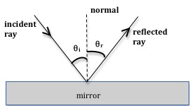
Figure 1: Reflection in a plane mirror
( 1 )
θi = θr
Refraction at a Plane Surface
When light is incident on the boundary between two optical media such as air and glass, some of it is reflected at the boundary, and some of it passes through and is refracted (bent), as shown in Fig. 2.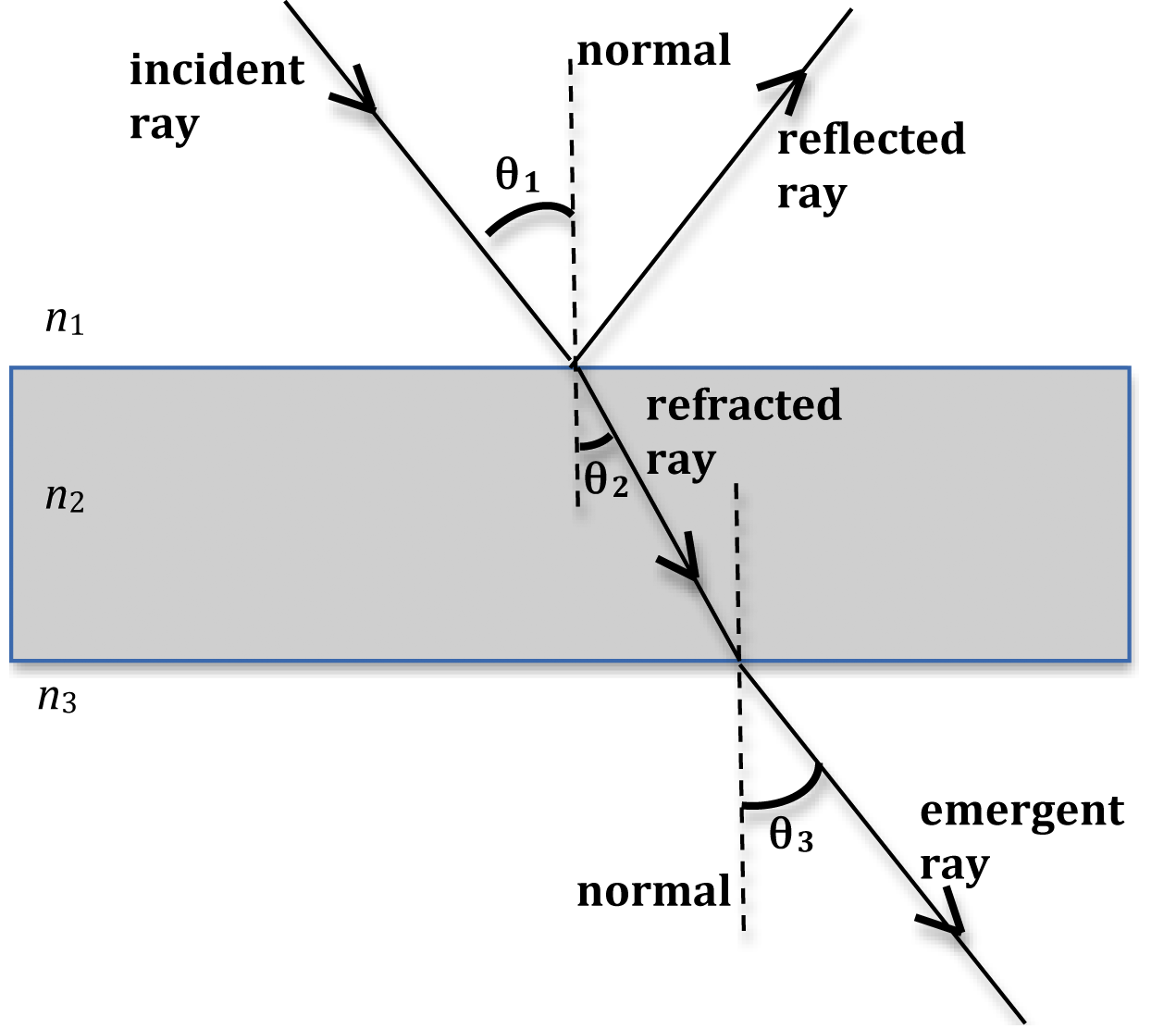
Figure 2: Reflection and refraction of light at air-glass and glass-air boundaries
(n1 < n2)
it will bend toward the normal. The angle of refraction θ2
in the second medium will be less than the angle of incidence θ1
in the first medium. On the other hand, when light goes from a denser medium into a rarer medium (n1 > n2),
it will bend away from the normal.
In Fig. 2, light is traveling from air into glass and then emerges back into air. Here n1 < n2
and therefore the refracted ray bends toward the normal. This refracted ray now goes from glass (denser medium) into air (rarer medium) and therefore it bends away from the normal. The angle θ2
between the refracted ray and the normal line is referred to as the angle of refraction.
The law of refraction is given by Snell's Law, which stated mathematically is
( 2 )
n1 sin θ1 = n2 sin θ2
( 3 )
n2 sin θ2 = n3 sin θ3.
n3
equals n1
as in Fig. 2, then θ3
will equal θ1
and Eq. (3)n2 sin θ2 = n3 sin θ3.
is essentially the same as Eq. (2)n1 sin θ1 = n2 sin θ2
. Also note that the emergent ray is parallel to the incident ray but shifted laterally to the right.
Unless a surface is highly polished, some of the light incident on a surface will be reflected and some part of it will be refracted. In Fig. 3 the incident ray is reflected off the front and back surfaces of the glass plate. The separation distance between the two reflected rays will depend on the thickness of the slab t and the angle of incidence.
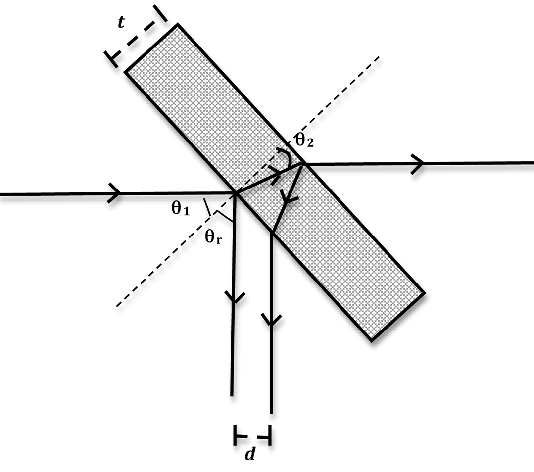
Figure 3: Sketch showing path of rays through glass plate
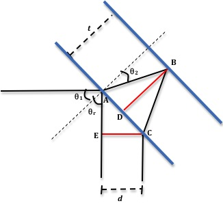
Figure 4: Sketch showing geometry of the setup
θ2.
ADB is a right triangle and, therefore, we have
( 4 )
tan θ2 = AD/BD.
θ1
and θr
are equal and, therefore, we have angle CAE = 90 – θ1. From this it follows that in the right triangle AEC, angle ACE = θ1,
which gives us
( 5 )
cos θ1 =
=
.
| EC |
| AC |
| EC |
| 2AD |
tan θ2 = AD/BD.
and Eq. (5)cos θ1 =
=
.
| EC |
| AC |
| EC |
| 2AD |
( 6 )
tan θ2 =
=
.
| EC |
| 2 cos θ1 |
| 1 |
| BD |
| d |
| 2t cos θ1 |
Objective
The objective of this experiment is to study the path of light rays due to reflection and refraction at plane surfaces and to verify the Law of Reflection in a plane mirror and Snell's Law of Refraction.Equipment
- Glass plate
- Laser
- Optic bench
- Vernier caliper
- Angular translator
- Rotational stage
Procedure
Please print the worksheet for this lab. You will need this sheet to record your data.
Description of Apparatus: Laser
We will use a HeNe laser with a wavelength of 632.8 nm. The power output of the laser is less than 1 mW so it cannot be used to burn holes in pieces of paper. However, it is sufficiently bright that it might cause eye damage if you stare into it.Caution:
DO NOT STARE INTO THE LASER OR ITS REFLECTION.
DO NOT STARE INTO THE LASER OR ITS REFLECTION.
Description of Apparatus: Optical Bench
The optical bench has a scale along one edge—this edge should be facing you. The back edge of the bench is raised slightly and should be used to align everything placed on the bench. All of the optical equipment (laser, component carriers, angular translator) have metal strips attached to them and will, therefore, stick to the magnetized surface of the bench. Fig. 5 shows a photo of the optic bench.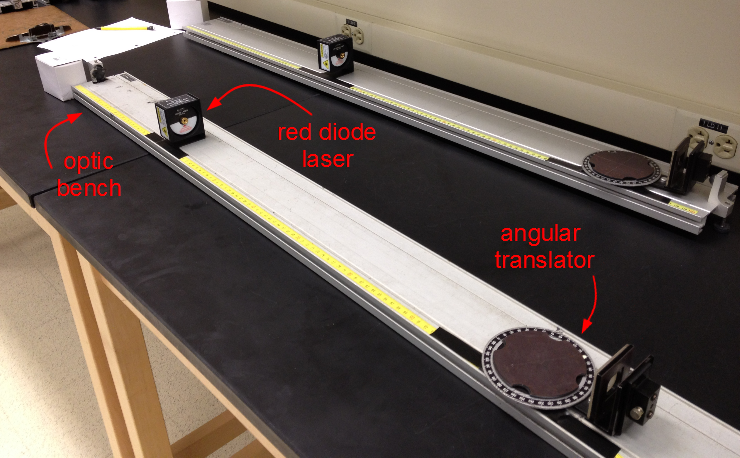
Figure 5: Optic bench
Description of Apparatus: Angular Translator
The angular translator is used to align optical components to within one degree. The top surface rotates so that an object can be moved through a certain angle. The translator also has a "stage holder" that rotates around the outside of the translator. This "stage holder" will be used to hold a scale. The photos below show two views of the translator and the stage holder.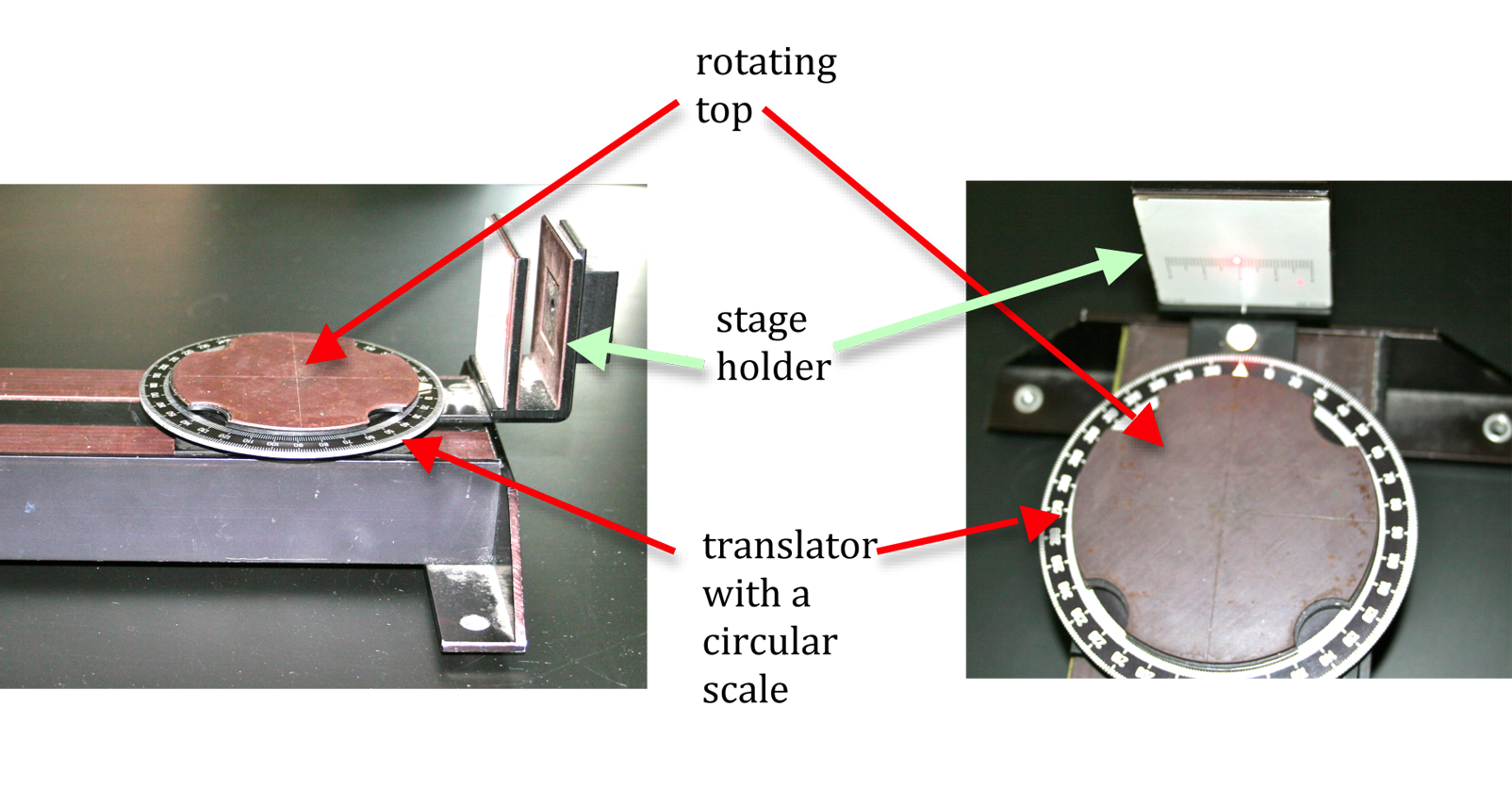
Figure 6: Side and top views of the angular translator
Alignment of Apparatus
1
Set up the laser at the right end of the optical bench and the rotational stage at the left end of the bench with the 0° mark toward the laser. Make sure both pieces of equipment are flush against the raised back edge of the bench.
2
Turn the rotational stage until the arrow indicates exactly 0°.
3
Position the glass plate on the stage so that the laser beam is reflected from the front surface of the plate straight back onto the face of the laser.
The glass plate must be positioned so that its front surface is directly over the center point (pivoting point) of the stage. This assures us that the laser beam will always strike the glass plate at the same place as you rotate the stage (see Fig. 7).
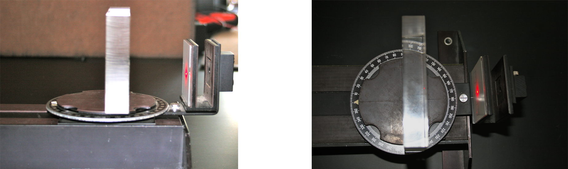
Figure 7: Side and top view of glass plate on rotating surface
4
Now if the rotational stage is turned, the angle between the laser beam and the normal to the glass plate will be the angle indicated by the arrow on the stage—this is the angle of incidence.
Whenever the stage is set to 0° the laser beam should be reflected straight back onto the laser.
Once the apparatus is aligned you should not change the position of the laser or the position of the glass plate on the rotational stage. Fig. 8 shows the glass plate rotated through an angle θ.
The red line indicates the path of the light from the laser and the green line shows the position of the normal to the plate.
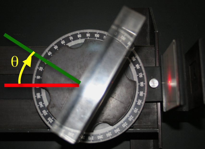
Figure 8: Photo showing rotation of glass plate
5
With the stage set to 0°, rotate the screen holder to 180°.
6
Place the screen on the screen holder and position the screen so that the laser beam passing through the glass plate strikes the screen at the center point on the scale.
No further adjustment of the screen should be made after this initial positioning.
Procedure A: Measurement of Angle of Reflection
7
Set the rotational stage to the desired angle of incidence θi
as described in step 4 and record this value in Data Table 1 on the worksheet.
8
Now rotate the screen holder until the laser beam reflected from the front surface of the glass plate strikes the screen at the center point on the scale.
9
The angle of reflection is the angular position of the screen holder minus the angular position of the rotational stage.
Measure and record the angle of reflection θr
for reflections from the surface of the glass plate.
10
Repeat steps 7 through 9 by changing θi
in increments of 10° on both sides of the laser beam.
11
Using Excel, plot the angle of reflection θr
versus the angle of incidence θi.
See Appendix G.
12
Model your results as θr = mθi + b
and use the linest function in Excel to determine m and b. See Appendix J.
Checkpoint 1:
Ask your TA to check your table values, graph, and calculations.
Ask your TA to check your table values, graph, and calculations.
Procedure B: Measurement of Index of Refraction
13
Measure the thickness t of the plate with the calipers and record it in Data Table 2 on the worksheet.
14
Where possible, use the same values for θ1
as you did for θi
in Procedure A. Make sure to use angles of incidence on both sides of the laser beam.
15
Repeat steps 7 through 10, but this time record θ1, d, and θ2
in Data Table 2.
Recall that d is the distance between the two reflected rays. The two red dots on the scale that is mounted on the stage holder (see Fig. 9) correspond to the images of the two reflected rays.
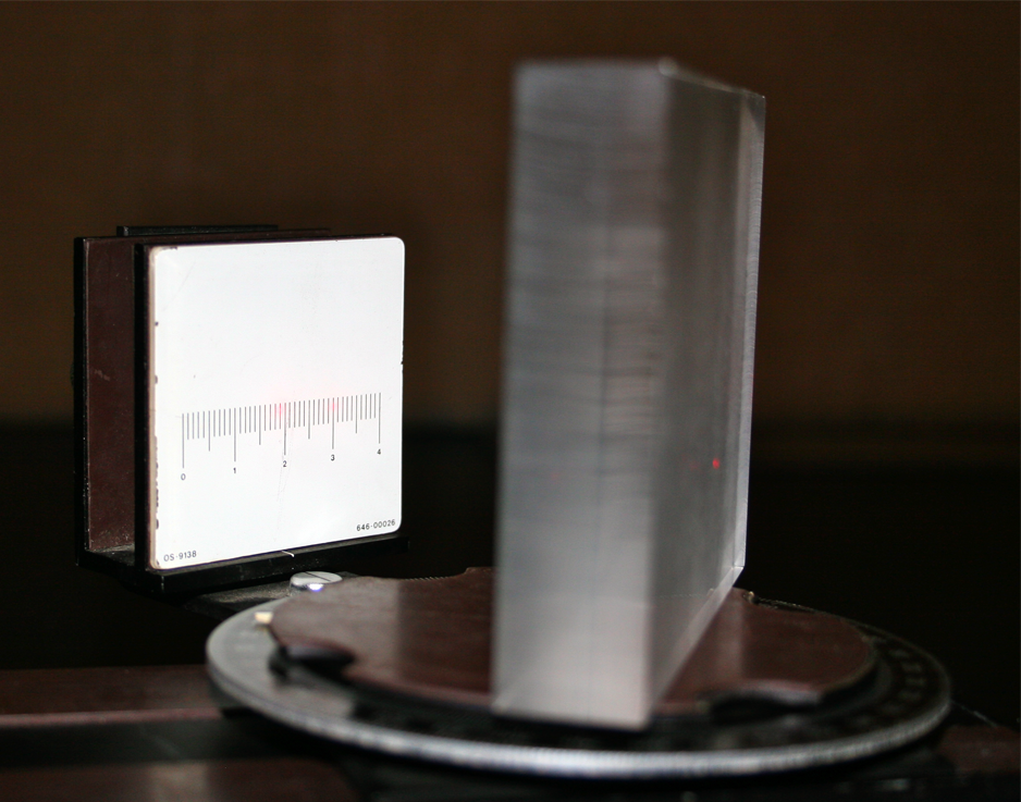
Figure 9: Photo showing the two reflected images on the scale
16
Use Eq. (6)tan θ2 =
=
.
and your experimental data to calculate | EC |
| 2 cos θ1 |
| 1 |
| BD |
| d |
| 2t cos θ1 |
sin θ2
for each incident angle and enter these values in Data Table 2.
17
Using Excel, graph sin θ1
versus sin θ2,
and determine the slope of the graph using the linest function.
18
From the slope, determine the index of refraction of the plate.
19
Calculate the percent error between the experimental value and the accepted value of nglass = 1.54.
Checkpoint 2:
Ask your TA to check your table values, graph, and calculations.
Ask your TA to check your table values, graph, and calculations.