
Lab 7 - The Magnetic Field of a Long, Straight Wire
Introduction
Magnetic fields are produced by current-carrying conductors. The presence of these magnetic fields can be detected and measured by the force they exert on other magnetic materials and current-carrying conductors. For example, when a compass is brought near a current-carrying conductor, the compass needle is deflected, thereby indicating the presence of a magnetic field. This connection between electricity and magnetism was first noticed by Hans Christian Oersted. Magnetic field has both direction and magnitude. The direction of the magnetic field surrounding a straight current-carrying conductor is given by the right-hand rule, and the strength of the field can be derived from Ampere's Law.Discussion of Principles
The magnetic field of a long, straight wire is given by( 1 )
B =
| μ0I |
| 2πr |
μ0
is the permeability of free space, I is the current flowing in the straight wire, and r is the perpendicular (or radial) distance of the observation point from the wire. Magnetic field is measured in units of Tesla (T). Note that the magnetic field B is inversely proportional to the distance r.
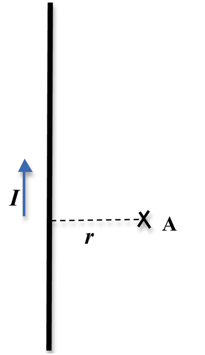
Figure 1: Current-carrying wire
B =
. If you consider a circle of radius r, the magnitude of the magnetic field will be the same at all points on this circle. Similarly, points on a circle of a different radius will have the same magnetic field. In other words, the pattern of the magnetic field due to a current-carrying wire is concentric circles centered about the wire.
| μ0I |
| 2πr |
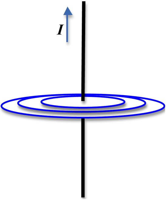
Figure 2: Magnetic field pattern due to current in a wire
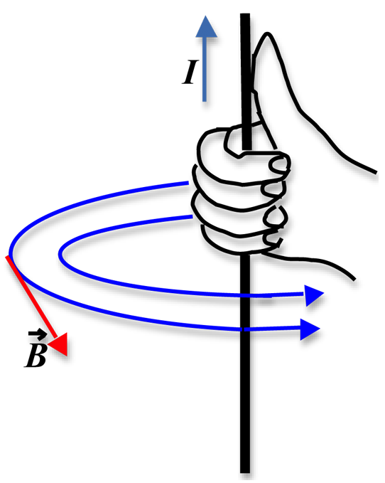
Figure 3: Using the right-hand rule
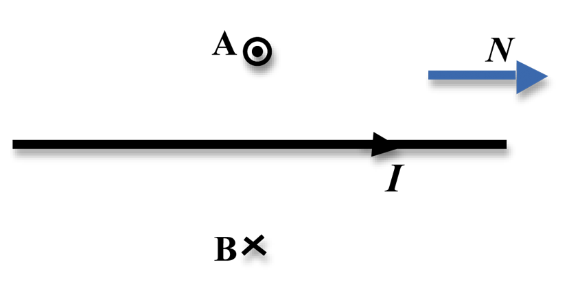
Figure 4: Magnetic field at two locations due to current in a wire
θ
to point in the direction of the net magnetic field. By measuring the angle of deflection and given that the horizontal component of the Earth's field is approximately 2.2 × 10⁻⁵ T (see Magnetic Field Calculator), we can calculate the magnitude of the field due to the current in the wire.
For any situation where Bwire and BE are perpendicular, Fig. 5 gives the direction of the net field.
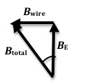
Figure 5: Combination of the two fields
tan θ =
,
and, therefore,
| Bwire |
| BE |
( 2 )
Bwire = BE tan θ.
Objective
The objective of this experiment is to establish the relationship between the field due to a current-carrying wire and the distance of the observation point from the wire and from that to experimentally determine the value ofμ0,
the permeability of free space.
Equipment
- Rectangular PVC frame
- Long wire
- Compass
- Power supply
- Styrofoam pieces
- Meter stick
- Multimeter
- Connecting wires
Procedure
Please print the worksheet for this lab. You will need this sheet to record your data.
1
Place the PVC frame on the corner of the lab table so that just one section of the rectangular loop of wire lies on the table.
2
Align the PVC frame and wire so that the wire and compass both point toward the north (see Figs. 6 and 7).
3
Determine the thickness of one piece of Styrofoam by stacking ten pieces, measuring the height of the stack, and dividing by ten. From this you can determine the height of the compass from the wire depending on the number of Styrofoam pieces you use.
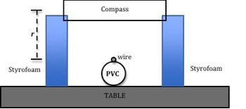
Figure 6: Sketch of end view of experimental set-up
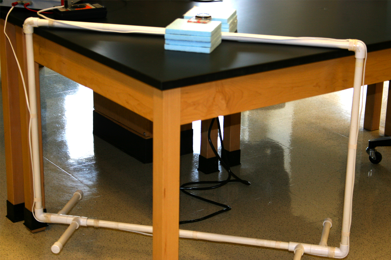
Figure 7: Photo of experimental set-up
4
The compass should rest over the red dot on the wire, supported on both sides by the pieces of Styrofoam. See Fig. 8.
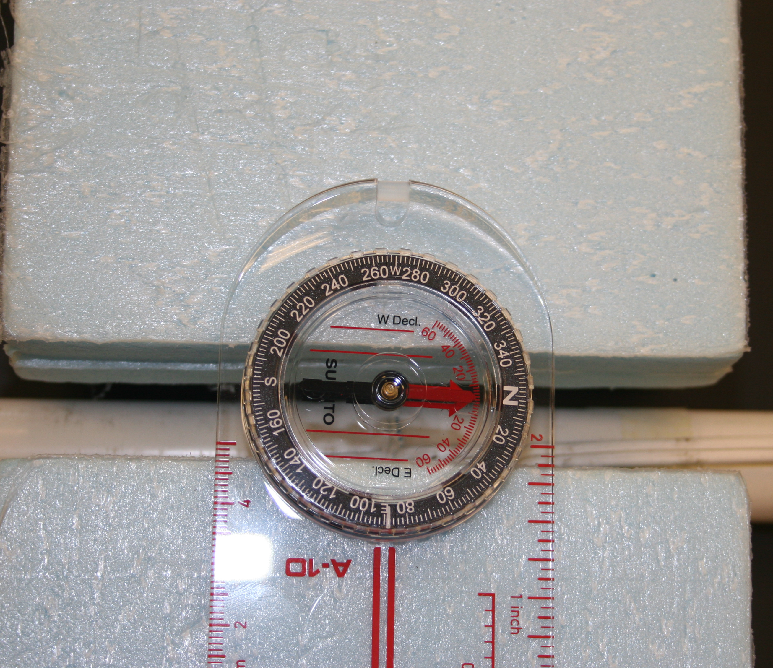
Figure 8: Top view showing orientation of compass and wire
5
Hook up the power supply, as shown in Fig. 9, in series with the wire and a multimeter. The multimeter will be used as an ammeter to measure the current through the wire.
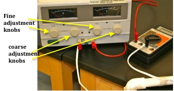
Figure 9: Circuit connections
Checkpoint 1:
Ask your TA to check your circuit connections.
Ask your TA to check your circuit connections.
6
Turn the power supply on and turn the "coarse" voltage knob about half way.
7
Use the "coarse" current know to adjust the current so the compass needle is deflected approximately 40°.
8
Adjust the "fine" current knob to make the compass needle deflect exactly 40°.
9
Record the current and its uncertainty on the worksheet. You can assume that the uncertainty in the current is 1%.
10
Add one piece of Styrofoam on each side. Record the deflection of the compass, keeping the current the same as in step 9.
11
Repeat this procedure twice more so that you have four distances and four deflections.
Checkpoint 2:
Ask your TA to check your values before proceeding.
Ask your TA to check your values before proceeding.
12
Assume the magnetic field has the form B = K rn,
where K =
.
We would like to find the value of n. If we take the natural log of both sides we get
| μ0I |
| 2π |
( 3 )
ln B = ln(Krn) = ln K + n ln r.
This is of the form of a linear equation,
y = mx + b,
where y = ln B, x = ln r,
the slope is n, and the intercept is ln K.
13
Use Excel to plot ln B versus ln r. See Appendix G.
14
Use the linest function in Excel to determine the slope, the intercept, and their uncertainties. See Appendix J.
Record these values on the worksheet.
15
Calculate n and its uncertainty from the slope of the graph.
16
The formula for uncertainty in μ0
is
( 4 )
σμ0 = μ0
.
 |
|


Define the intercept of the graph as b, then
K = eb
and σK
= σbK.
Use this information to calculate
μ0
and its uncertainty from the intercept.
17
Calculate the percent error between the experimental and accepted values of μ0.
See Appendix B.
Checkpoint 3:
Ask your TA to check your Excel graph and calculations.
Ask your TA to check your Excel graph and calculations.