
Rotational Equilibrium
Purpose
-
•To confirm that torque equals force times lever arm for a horizontal lever.
-
•To weigh an unknown mass with a beam balance.
-
•To determine the weight of the beam balance.
-
•To learn to calculate torque using the center of mass of an object, and to learn why this is possible.
-
•To analyze systems where the forces are not perpendicular to the lever.
Equipment
- Beam balance apparatus
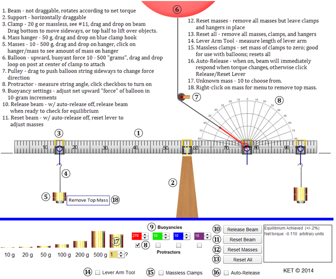
Figure 1: The beam balance apparatus
Simulation and Tools
Open the Rotational Equilibrium simulation to do this lab.Theory
Torque
Up to this point in physics, we haven't allowed forces to act in such a way as to cause rotation. The forces acting on a grocery cart traveling along an aisle could only be exerted in such a way that no rotation of the cart was produced. As you know from experience, this can be accomplished by pushing straight ahead on the center of the handle of the cart or by pushing equally on the two ends of the handle. (This assumes no wobbly, squeaky wheels—generally a bad assumption.) But as we know, bad things can happen at the end of the aisle when paths cross and carts can end up spinning off into the produce section. When this occurs, the cart moves along some new path and often spins. Forces that tend to cause rotation are said to apply a torque to the objects they act on. Consider the three forces, F, in Figures 2a–c. All three act in the plane of the page. The rod is hinged so that it can rotate around its axis of rotation, which is normal (perpendicular) to the page. Thus, the rod can only rotate in the plane of the page.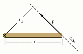
Figure 2a: Torque on a rod
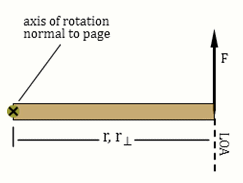
Figure 2b: Force perpendicular to r. Maximum torque.
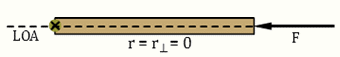
Figure 2c: Force collinear to r. Zero torque.
1
Under what conditions are r and r⊥ equal but nonzero?
Rotational Equilibrium
We know that a body with no net force acting on it will be in translational equilibrium and have zero translational acceleration. As shown in Figure 3a, two equal but opposite forces are able to cancel, resulting in no translational acceleration.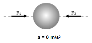
Figure 3a
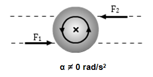
Figure 3b
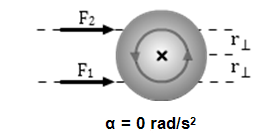
Figure 3c
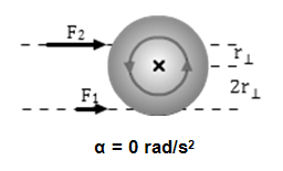
Figure 3d
F2 = 2F1.
Force F2 applies a negative, clockwise, torque of –r⊥F2.
Force F1 applies a positive, counterclockwise, torque of 2r⊥F1.
In this lab, we will be working with systems that are in rotational equilibrium; that is, where the vector sum of the torques about any axis equals zero. Equation 2 is called the Second Condition Equilibrium.
This is a vector equation where positive torques are defined as torques that would tend to produce a counterclockwise rotation and negative torques would tend to produce a clockwise rotation. Equation 2 can be used in ways similar to how we've used equation 3, the First Condition Equilibrium.
The two equations can also be used together in situations where forces act to put a system in both types of equilibrium. For example, when you lean against a wall, there are forces exerted on you by the wall, the ground, and Earth's gravity. If these forces and the torques they produce are not in balance, you will fall and spin on the way down!
Explore the Apparatus
Let's set up the apparatus just as it appears in Figure 1.1
Click on one of the four rectangular clamps at the upper left of the screen. Drag and release it somewhere on the left end of the beam. It will snap in place. Drag it and release it at about the 15-cm mark. (We'll work on precision in a moment.)
The beam should rotate counterclockwise, but it doesn't. The apparatus is designed to allow you to work with it as if your partner is holding it in place. Your "partner" can hold the beam steady and release it when ready in two ways.
-
•Click the Release Beam button. The left end of the beam will fall. Not far—your virtual partner caught it. Click Reset Beam to get your partner to hold it level again.
-
•The other method is Auto-Release. With the beam still horizontal, click the "Auto-Release" check box. The left end of the beam will fall. Drag the support left or right. While the support is selected, the beam will return to level so that you can better read it. Release the support and the beam will fall if it isn't balanced. The same goes for the clamps and hangers. Drag the clamp and then release it. The beam will become horizontal and then reset upon release. You'll probably want to use Auto-Release most of the time. I'll use that in these instructions.
2
Drag one of the four mass hangers, and drop it when it's over the clamp. It will snap to the clamp.
3
Add 300 g to the mass hanger. Click on the masses and note that the info box confirms that there's 300 g on the hanger. Note the masses of the clamps (20 g) and hangers (50 g) in the list of information in Figure 1. So, the total is 370 g.
What if you put too much mass on a hanger? Try this. Right click (Ctrl+click) on the masses on the hanger and click Remove Top Mass from the menu. This may come in handy later. OK, replace the mass you deleted.
4
We now want to add a second clamp at 94.4 cm. Start by placing it at 94.0 cm. Using Figure 4a as a guide, do your best to place a hanger there. For a better view, right click (Ctrl+click) on the clamp and Zoom in to make fine adjustments. If you Zoom in about three levels you'll notice that there is a tiny set of 1-mm graduations inside the mass hanger clamp. See Figure 4a. You can even see them through a transparent section of the hanger. Drag the hanger left and right. Notice that the graduations are attached to the clamp not the meterstick. So they move against the background of the widely-spaced 1-cm marks. These millimeter marks tell you how far the clamp is away from a 1-cm mark.
In Figure 4a, the clamp is at 94.0 cm. Adjust yours to match. Notice how the central 1-mm mark, which defines the location of the hanger, aligns with the long 94.0-cm mark on the ruler. And there are 10 1-mm marks either side of it for the full 2-cm width between 94.0 and 95.0 cm.

Figure 4a: 94.0 cm; Millimeter Scale Close-Up Image

Figure 4b: 94.4 cm; Millimeter Scale Close-Up Image
Carefully drag your clamp one millimeter to the right. A new 1-mm mark is now aligned with the 94.0-cm mark. Repeat for 2, 3, and then 4 mm. With each additional millimeter a new 1-mm mark will align with the 94.0-cm mark. Once you have moved the clamp 4 mm, the view should match Figure 4b. It's sort of counterintuitive, but it works.
Now would be a good time to check to see if your other clamp is at 15.0 cm. You can either drag the enlarged apparatus to the right until you get there or Zoom out and then back in. You might also notice on the way that the meterstick holder clamp has a similar millimeter scale.
Zoom back out. Add a hanger and 400 grams to the clamp. The beam almost balances when you drop the first 200 grams on. So the second one puts it way out of balance.
5
We'll use an upward force on the right side to bring the beam into equilibrium. Add a clamp at 88.0 cm.
6
Drag the red ring hanging from a string and release it to let it attach to the clamp pin. The pin is at the center of the clamp. You'll now see a helium-filled balloon near the top of the screen. It's pulling upward on the beam, but not hard enough to balance it.
7
Just below the beam support, you'll see "Buoyancies." Click the up arrow beside the 10 in the red box. (These are called numeric steppers.) It will increase to 12 and the balloon will expand a bit. This will add some "lift," but not enough.
Caution:
The "12" should be interpreted to mean an upward force equivalent to the weight of 12 grams. This brings us to a special bit of notation that we'll be using in this lab. It's very convenient and, some would say, odd. Here's how it works. As torque is the product of length and force, we should measure length in meters and force in newtons. The length part is simple enough.
Also, we're using traditional masses labeled in grams, which need to be adjusted to kilograms. Easy again.
But when we multiply by g (9.8 N/kg), we get
This is not quite so easy, so we want to simplify the calculation of 0.400 kg → 3.92 N.
Instead of multiplying by g, we'll write the force as 0.400 g N.
"0.400 g N" will be our shorthand for 0.400 kg × g newtons; that is,
The "12" should be interpreted to mean an upward force equivalent to the weight of 12 grams. This brings us to a special bit of notation that we'll be using in this lab. It's very convenient and, some would say, odd. Here's how it works. As torque is the product of length and force, we should measure length in meters and force in newtons. The length part is simple enough.
25 cm = 0.25 m
400 g = 0.400 kg
0.400 kg × 9.8 N/kg = 3.92 N.
0.400 kg × 9.8 N/kg = 3.92 N.
So, our reading of 12 for the balloon's lift force will be recorded as a force of 0.012 g N.
8
Add helium until you get the beam in balance. When you get close, you'll see that there is a range of values that will get the beam to within 0.2% of balance and remain horizontal. See the reference to this in the info box. If balances were ideal (that is, if they would only remain horizontal when the net torque was exactly zero), we would never get them in balance. Fortunately, in our nonideal world, friction at the pivot will allow the beam to stay horizontal if we get to within some small range of balance. This apparatus is designed to work in that fashion. Adjust the helium to produce the smallest magnitude (-0.544, –0.054, 0.4380) net torque. (Now your three torques all add to about zero.)
9
Note the pulley attached to the side of the upward string. Don't touch it yet! What will happen to the beam if you push the pulley to the left? Why? Think about components of the tension in the string.
10
Will the result be different for a push to the left vs. a push to the right? (Assume equal angles.) Why?
11
Try it in both directions. Note that the farther you push it sideways, the quicker the right end of the beam falls.
For the following, push the pulley to the left to an angle similar to the one in Figure 2a.
Look at the angled string. The force it exerts on the clamp is directed along the string. Now imagine the string as a force vector, up to the left. Form a mental image of the x- and y-components of the tension.
When the beam is in equilibrium, that is, horizontal, the line of action of the horizontal x-component, Tx, passes directly through the rotation axis (×). Thus, its lever arm is zero and it produces zero torque as shown in Figure 2c.
The line of action of the vertical y-component, Ty, is perpendicular to the beam. Its lever arm is the maximum possible length and produces the maximum possible torque.
At what angle relative to the beam would that force, Ty, be equal to half of T?
12
Click the "Protractors" check box below the red "Buoyancy" numeric stepper. Click on the pulley and adjust the string to the angle you chose in step 11.
13
What buoyant force from the balloon will now be needed to balance the beam?
Try it.
14
Before we leave this exploration, we need to take a look at the signs or directions associated with torque. We've mentioned this a couple of times but never explained it. The direction of a torque is, oddly, perpendicular to the plane of r and F. For example, if r and F were in the plane of this page we would say
-
•a torque that would tend to cause r to rotate clockwise (cw) is a negative torque, and its direction is into the page.
-
•a torque that would tend to cause r to rotate counterclockwise (ccw) is a positive torque, and its direction is out of the page.
Procedure
Please print the worksheet for this lab. You will need this sheet to record your data.
I. Confirm that Torque = Force Times Lever Arm for a Horizontal Lever
Click Reset All to make sure that the apparatus is in its default arrangement. Leave "Auto-Release" on.
1
Drag and drop to attach a clamp at 0 cm. Attach a mass hanger to the clamp. This is Hanger 1.
2
Add enough masses to the hanger for a total mass of 100 g, including the clamp, hanger, and added mass. Since the clamp's mass is 20 g and the hanger's mass is 50 g, you'll need to add just 30 g.
The 10- and 20-g masses are hard to grab. You can just grab the "10 g" and "20 g" labels below the mass images for convenience. Click on the masses on the hanger. The information box will read "Mass on this hanger = 30." Don't forget to count the other 70 g when determining the total mass.
3
In Trial 1, the given value of 1.00 m in the first position column tells you to add a second clamp and mass hanger (we'll call it "Hanger 2") at 100 cm. Then, following the order provided (a, b, c, d), determine each successive value theoretically, by calculation, and then experimentally.
For Trial 3, show your calculations of the weight required to balance the beam.
| weightleft × lever armleft | = | weight (theoretical)right × lever arm (given)right |
| weight (theoretical)right | = |
4
In Trials 4–5, you're given known weights for the right hanger. You'll then adjust its hanger position to achieve balance.
5
In Trial 4, the known value of 0.200 g N for the weight tells you to adjust the weight on the right hanger to provide a total hanger weight of 0.200 g N. Then, following the order provided (a, b, c, d), determine each successive value.
For Trial 5, show your calculations of the position of the hanger required to balance the beam.
II. Weighing an Unknown Object
All of us have had the opportunity to be the "unknown weight" in the doctor's office. The scales traditionally used work much like the one we're working with. They just look different because there are some extra levers inside to allow it to balance your weight with the very small weights on the other side of the fulcrum.
Click Reset All to make sure that the apparatus is in its default arrangement. Leave the support at the 50-cm point.
1
Attach a clamp and a hanger at a point somewhere to the left of the support stand. This is Hanger 1.
2
The right-most mass in your mass set will act as our unknown. We want to determine its weight. Using the selector below the unknown mass, select any number from 2–10. (A particular number may be assigned to you.) Record the selected unknown mass number.
3
Drop your unknown mass on Hanger 1.
4
Attach a clamp and Hanger 2 somewhere to the right of the support stand.
5
You now want to bring the beam into balance. To do this, you can adjust the position of either mass. You can also adjust the weight on Hanger 2.
6
Clearly show your weight and lever arm data by adding information to Figure 5. The unknown weight doesn't include the clamp and hanger. (You don't want your boots and backpack counted when you're weighed!)
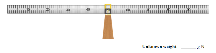
Figure 5: Unknown weight data and calculations
7
Record your value for the unknown weight in the space provided.
8
Show your calculations in WebAssign.
III. Determine the Weight of the Beam
1
Reset All and turn on "Auto-Release." Now drag the support over to the left a bit. Obviously, the beam's weight provides some amount of torque. And also obviously, its net effect was zero until we moved the support.
2
Drag the support to the 20-cm point. Zoom in to get it just right.
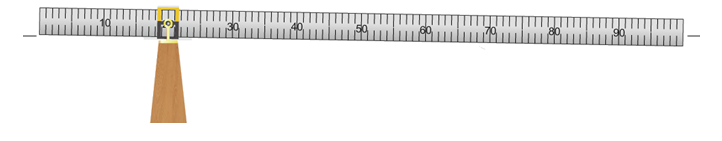
Figure 6
3
The beam is way out of balance. To bring it back into balance, place whatever masses are needed at the 0-cm point.
4
What total weight was required, including the clamp and hanger?
Equation for Torque Due to a Thin Rod of Uniform Density
We need to divide the meterstick up into zillions of tiny segments, each with tiny masses. Then we'll add the torques due to each of these little segments. Calculus lovers, this is for you. Everyone else, don't panic about this derivation. I'm going to explain it as best I can, but there's magic at the end. And it's been a very long time since I've done magic. In Figure 7a, you see our rod divided into lots of tiny segments, which we can make as small as we like. Each segment is identical in length and, hence, mass and weight. The axis of rotation is at the left end. The torque due to each segment equals its weight, wi, times its lever arm, ri. We'll describe the weight in terms of the length using the linear density, μ, which is the mass/length in kg/m (e.g., a 2-cm section will have a mass of (0.02 m)(μ kg/m)).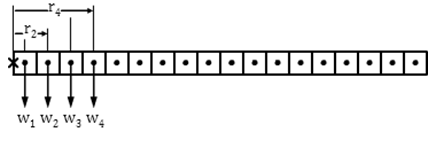
Figure 7a: Torque of a thin rod about one end
τ = r1w1 + r2w2 +  + rNwN = r1m1g + r2m2g + + rNmNg
+ rNwN = r1m1g + r2m2g + + rNmNgτ =
=
= μg
.
| N | riwi |
 | |
| i = 1 |
| N | rimig |
| |
| i = 1 |
| N | riΔr |
| |
| i = 1 |
lever arm × the mass × g, which is the torque for a small section. We need to convert this infinite sum to an integral to produce an equation. That looks like the following.
τ = μg
= μg
| L | rΔr |
 | |
| 0 |
| r2 |
| 2 |
 | r = L |
| r = 0 |
τ = μg
= μLg
= W
| L2 |
| 2 |
| L |
| 2 |
| L |
| 2 |
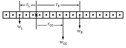
Figure 7b: Torque of a thin rod about a point along the rod
WL =
Wb
| 5 |
| 18 |
WR =
Wb.
| 13 |
| 18 |
τ = r⊥F
) for each segment of width ws, and considering the positive and negative directions of the counterclockwise and clockwise torques respectively,
τL = −WL × rL =
Wb × 2.5ws
| 5 |
| 18 |
τR = WR × rR = −
Wb × 6.5ws.
| 13 |
| 18 |
| = | τL + τR =
| ||||||||
| = |
| |||||||||
| = |
| |||||||||
| = | −
|
Important Punchline:
If you know the location of the center of gravity of an extended body, you can treat it as if all its weight acts at that point for the purpose of calculating torques.
If you know the location of the center of gravity of an extended body, you can treat it as if all its weight acts at that point for the purpose of calculating torques.
5
Calculate the weight of the beam.
Show your calculations of the weight of the beam.
6
Calculate the torque due to the weight of the beam.
Show your calculations of the torque due to the weight of the beam.
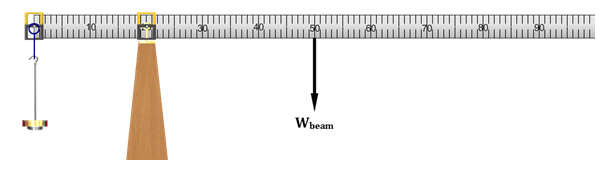
Figure 8
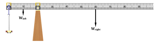
Figure 9
7
To find the weight of each end, we need the linear density, μ. The linear density is the mass/length for the beam. You know both its mass and length now.
Show the calculations.
8
The left end of the beam is 0.200 m long. Using mass = μ × length, determine the mass of the 20-cm left end.
9
The center of gravity of the left end is at the center of this 20-cm section. Record this value.
10
Similarly, find mright end and the lever arm of right end.
11
Calculate the ccw torque and cw torque with this new configuration of the beam. As before, we'll ignore the mass hangers. We just want the total torque due to the two ends of the beam.
Show your calculations of the positive counterclockwise and negative clockwise torques and the net torque.
12
How do the results of the two methods of calculating the torque due to the weight of the beam compare?
IV. The Torque Due to Forces Not Perpendicular to the Lever
You saw in the exploration section that a force will produce its maximum torque when it acts perpendicular to the "lever." That is, when it acts perpendicular to r. (See Figures 2a–c.) But in many cases, that's not the most convenient choice. The weight of the sign in Figure 10 produces a cw torque that must be countered by an equal ccw torque. The guy wire supplying this torque would be under the least tension if it acted horizontally (Wire 1). But they often need to be attached to the ground (Wire 2). Thus, they're under a larger tension due to the reduced lever arm. This arrangement requires thicker wires, strong anchors, etc.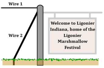
Figure 10
a
a vector perpendicular to the plane formed by the two vectors.
In our case, the new vector is the torque and its direction is out of the page (+) when the force tends to cause a counterclockwise (ccw) rotation and into the page (–) when the force tends to cause a clockwise (cw) rotation.
b
equal to the product of the magnitudes of the two vectors times the sign of the angle between them.
In the case of torque, that product is given by
where θ is the angle between r and F.
It's fairly simple to think about increasing the amounts of quantities like mass, force, length, brightness, current, etc. Just push harder, etc. But with torque, the sin(θ) term plays a very big role, and it's not so intuitive. And there are a lot of situations such as the one in Figure 10, where we have to make smart design decisions.
It's useful to think about the equation for torque in one of two different ways, depending on the situation. Figures 10a and 10b illustrate the same torque, but are drawn to emphasize two different ways of thinking about how the torque would change with changes in the direction of the force. In both cases, F and r are the same. But the torque changes as we vary the angle, θ, between F and r. It can be helpful in some cases to think about how changing θ changes the magnitude of F sin(θ), the force perpendicular to r. In other cases, it's more helpful to think about how changing θ changes the lever arm, r⊥.
Remember from Figures 2a–c that the torque equals the product of the force and the lever arm, and the lever arm is the distance between the rotation axis and the line of action of the force.
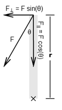
Figure 10a
Case I:
As θ increases, F⊥ becomes longer, indicating a larger horizontal force.
τ = rF sin(θ) = rF⊥
The force, F, can be represented in terms of its two components, F sin(θ) and F cos(θ). The total torque would be the combined effect of the torques of these two components. Add the line of action and lever arm for each force to the figure.
Mentally animate the figure by rotating F through angles from θ = 0° to 90° and observing F|| and F⊥.
F|| = F cos(θ) is the component of the force collinear with r and as a result passes through the axis and has no lever arm. Thus, F|| produces no torque.
F⊥ = F sin(θ) is the component of F perpendicular to r and thus provides a torque of
( 6 )
τ = r(F sin(θ)) = rF⊥.
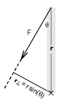
Figure 10b
Case II:
τ = r sin(θ)F = r⊥F
The lever arm, r⊥, is the shortest distance between the chosen rotation axis and the line of action of the force. The torque equals the product of the lever arm, r⊥, and the force, F. As θ changes, the lever arm, r⊥ of the force F increases from r⊥ = 0 to r⊥ = r.
Mentally animate the figure by rotating F through angles from θ = 0° to 90° and observing r⊥.
r⊥ = r sin(θ) is the component of r perpendicular to F and, thus, provides a torque of
( 7 )
τ = r sin(θ)F = r⊥F.
Modeling a Construction Crane
With just a little imagination, we can produce a pretty good model of a construction crane with our apparatus. (Google "construction crane" for a lot of nice images.) Ours is a tower construction crane.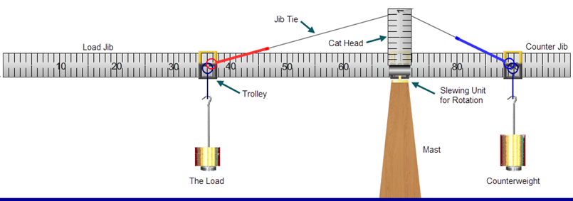
Figure 11
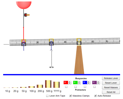
Figure 12
1
Reset All. Turn on "Auto-Release."
2
Turn on "Massless Clamps." This means that the clamp's mass is now 0 grams rather than 20 grams.
3
Add a clamp and mass hanger at the 30-cm point. Add 150 g for a total of 200 grams. We'll leave this as a constant setting in this section of this activity. It will produce a constant known torque to balance a counter-torque, which we'll produce while varying the tension in the jib tie cable and the angle of that cable.
4
Add a clamp at the 10-cm point.
(For insurance purposes, be sure to zoom in and get things just right. There are spectators down there—mostly envious men wanting to check a big item off their bucket lists.)
5
We need a clockwise torque to balance the 200-g mass. Thus, we need an upward force. Drag the loop of one of your balloons and attach it to the clamp at 10 cm. Nothing will happen because the balloon doesn't supply enough buoyant force to counter the torque of the 100-g mass.
6
Adjust the balloon's numeric stepper until the beam comes into balance.
You should find that 100 grams is required for balance. Here's the math.
τclockwise = −τcounterclockwise
Or, using absolute values:
|τclockwise| = |τcounterclockwise|.
Omitting the ||'s:
| (rballoon⊥)(Fballoon) | = | (rhanger⊥)(Fhanger) |
| (0.400 cm)(0.100 g N) | = | (0.200 cm)(0.200 g N). |
7
Grab the pulley by its wooden handle
-
•The y-component, F⊥, of the tension force is reduced.
-
•The lever arm, rballoon⊥, is reduced.
8
To measure our angles, we'll need a protractor. Click the check box under your balloon's mass stepper.
Pull the string over to 60°. Is θ = 60°? No. (See Figure 16.)
In the torque equation, θ is the angle between r and F, where r is a line from the center of the support pivot out to where the string attaches to the clamp, and F is the force provided by the string tension. So θ is the compliment of 60°. We'll call the 60° angle read from the protractor Φ. You'll record both angles in Table 3.
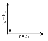
Figure 13
9
Adjust the pulley to Φ = 0°. This is the first entry in the Table 3 in WebAssign. We've already looked at this case and done the calculations for Case I in step 6, so you should be able to fill in all but the last two columns in the first row. Note that the last five columns are designed to differentiate between Case I and Case II discussed earlier.
10
The last two columns are also simple for this first case. In this case, r⊥ = r, so you know r⊥. And you know Fb.
You should find that your torque values in columns 6 ((r)(F⊥)) and 8 (r⊥Fb) are equal.
τ = rF sin(θ) = rF⊥
-
•Variation in torque due to change in F⊥
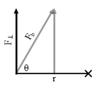
Figure 14
11
For Trial 2, adjust the pulley so that θ is 60° as shown in Figure 14 and listed in Table 3. Clearly the beam is no longer in balance. Add helium to the balloon until equilibrium is again achieved. It won't take much. Figure 14 should show why. Record the new Fb value.
The beam is now back in balance. What happened to rF⊥ to bring it back to equilibrium? r is still the same. It would only change if we moved the hanger. So, it must be F⊥ that changed. F⊥ now equals the original Fb, 100 g N.
Fb is directed along a line going up to the pulley. The magnitude of F⊥ is equal to the side opposite θ. But it acts at the location shown in the figure. As we increased Fb, F⊥, the component of F perpendicular to r, increased proportionally.
F⊥ = Fb sin(60°)
12
Record F⊥, and r, which is still 0.4 m. Calculate and record rF⊥ in Table 3.
τ = r sin(θ)F = r⊥F
-
•Variation in torque due to change in r⊥
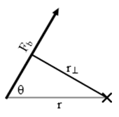
Figure 15
13
The system was initially in balance, but then we changed the angle and had to increase Fb to restore balance. The actual force, F, acting is Fb. So something had to decrease to keep the torque equal to 0.040 g m N. r is clearly still 40 cm, but what is r⊥, the lever arm of the tension in the string which we're calling Fb?
The lever arm is the shortest distance between the axis at the support pivot and the LOA of Fb. It will always strike the LOA at a right angle.
14
We need to measure the lever arm, r⊥. Click the check box beside the "Lever Arm Tool." A tape measure will appear. Click and drag the black rectangle up to the left. Adjust the tape so that it's perpendicular to the string. The distance it measures should be equal to about r sin(60°). Calculate and record that value in the table. Does the ruler's value agree?
15
Continue with the rest of the table by adjusting θ to the angles 45° and 60°. Hopefully, your torques will all agree. They should, since they are always being used to balance the torque provided by the mass hanging at 30 cm.
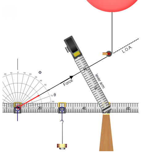
Figure 16: Use of the lever arm tool