
Angular Impulse and Angular Momentum Change
Objective
In this lab you will:-
•use measurements to relate the angular impulse τAΔt to a change in angular momentum ΔL,
-
•and do a similar experiment using the Angular Momentum Principle (ΔL = τAΔt) to determine the unknown moment of inertia of a composite object.
Some useful equations and constants are given at the end of this document.
Equipment
- PASCO rotational apparatus
- Smart pulley
- PASCO ScienceWorkshop® Interface
- Ruler
- Balance
Procedure
Please print the worksheet for this lab. You will need this sheet to record your data.
Due to the nature of this lab, you will be recording your data, calculations, and graphs in an Excel® spreadsheet. You will upload this spreadsheet in WebAssign.
Setup
Equipment Setup
The apparatus should be set up as in Figure 1.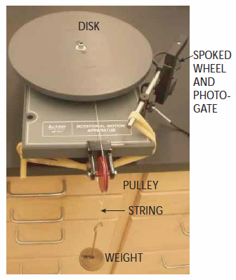
Figure 1
1
On the bottom of the disk, there are three grooves. Wind the string around the grooved disk with the smallest radius. Make sure the black-spoked wheel is touching the large disk (use the rubber band to hold it in place).
2
Hang the mass from the end of the string. Do not put any extra masses on the hanger – just use the hanger itself.
3
Release the mass. The mass should fall, and the big disk should spin faster and faster.
4
As the big disk turns, the small black spoked wheel should also turn. This allows the computer to
provide the instantaneous tangential speed of a point on the rim of the black wheel (using the radius of the wheel).
Capstone Setup
1
Download and open the appropriate Capstone file for this experiment.
2
You should see a display that includes a single window containing an empty graph, with y-axis labeled linear speed m/s.
Coordinate System
Using our usual coordinate system (x to the right, y up, z toward you), the big disk rotates in the xz-plane, so its angular momentum will be in either the +y- or –y-direction. The torque exerted on the disk by the hanging weight will also be in the +y- or –y-direction.Role of the Pulley and Tension of the String
As long as friction with the axle and the moment of inertia of a pulley are small, little net torque is needed to make the pulley spin faster, so the tension in the string is nearly the same on both sides of the pulley. Therefore, the force exerted by the string on the big disk (the "tension" force) is nearly the same as the force exerted by the string on the hanging mass. When we release the mass, it starts from rest and then speeds up, so However, the rate of change of momentum of the mass is small (it speeds up, but not much), so we can safely make the approximation thatTorque
Remember that the definition of torque around a particular point A is We will take the center of the big disk to be location A. The y-component of torque, therefore, is Imagine that the big gray disk is transparent, and you are standing on the +y-axis, looking down at the disk. The diagram in Figure 2 is drawn from that perspective, with +x to the right, +y out of the page toward you, and +z down. The string is wrapped around the smallest grooved disk.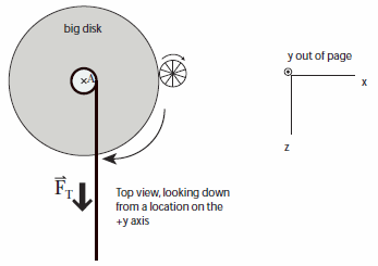
Figure 2
Initial Measurements
Moment of Inertia of the Large Gray Disk
1
Measure the quantities that are necessary to calculate the moment of inertia of the gray disk, and
record the data and calculation. For a disk of uniform density, I =
MR2.
| 1 |
| 2 |
Determining the Change in Angular Speed of the Disk
Capstone will make a plot of the tangential speed of a point on the rim of the spoked wheel as a function of time. Since this is the same as the speed of a point on the rim of the big disk (think about the point where they touch!), you can use this relation to calculate the angular speed of the big disk1
Measure the quantities that are necessary to calculate the angular speed of the big disk. Record your
data and calculations.
2
Click Record in Capstone, then release the mass and let it fall. Do not stop until the string has unwound completely, then rewound as the spinning disk pulls the mass back up.
Your graph of v vs. time should have two segments: one with positive slope (speed increasing, mass falling) and one with negative slope (speed decreasing, mass rising). Note that the magnitudes of these slopes are different. You should have seen the same effect in the Fan Cart lab earlier in the semester.
3
Click the "Data Coordinates" tool, the choose Add coordinates delta/tool as shown in Figure 3. Use the coordinates tool to read two values of speed, measured across the same time interval (e.g., 2 seconds), from each segment of your graph, and record these in your spreadsheet.
4
Calculate the change in angular speed of the disk over each of these two equal time intervals.
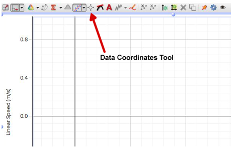
Figure 3: Data Coordinates Tool
Determining Torque
1
Measure the quantities that are necessary to calculate the y-component of the torque exerted on the disk by the string, as the mass falls. Record that data and calculation.
Note that there is friction in the system; the torque due to the hanging mass is not the only contribution to the torque.
Checkpoint:
Compare your data with another group to make sure it is reasonable.
Compare your data with another group to make sure it is reasonable.
Relating Angular Impulse τΔt to Change in Angular Momentum
Change in Angular Momentum
1
Use your results from "Initial Measurements" to calculate the change in the y-component of rotational angular momentum of the disk over each time interval (mass falling and mass rising). Record your calculations.
Angular Impulse
2
Use your results from "Initial Measurements" to calculate the y-component of angular impulse due to the hanging mass over each time interval (mass falling and mass rising). Don't forget to think about the direction. Record your calculations.
Taking Angular Friction into Account
When the mass is falling, the torque due to the mass acts to speed up the disk, but the frictional torque acts to slow it down. That is, if the torque due to the mass is in the +y direction, the frictional torque is in the –y direction. In terms of magnitudes, However, when the mass is rising, both the torque due to the mass and the torque due to friction are in the same direction, and act to slow down the disk. In terms of magnitudes, In other words, the friction decreases the magnitude of the net torque when the mass is falling, but it increases the magnitude of the net torque when the mass is rising. Notice that by recording information for the mass falling and rising for equal Δt's, we can factor out the effect of friction. All we need to do is average the magnitude of angular impulse for the two cases! Make sure you understand why before continuing. As long as Δt is the same for each interval!1
Calculate the average of the magnitudes of the changes in rotational angular momentum of the disk (taken over both time intervals).
Caution:
Make sure you average the magnitudes of the two ΔL's.
Make sure you average the magnitudes of the two ΔL's.
Checkpoint:
Compare your work with another group to make sure you agree. Then answer the follow-up questions for this section in WebAssign.
Compare your work with another group to make sure you agree. Then answer the follow-up questions for this section in WebAssign.
Determine an Unknown Moment of Inertia
1
Place the large rectangular piece over the gray disk, and repeat the measurements you made in
"Determining the Change in Angular Speed of the Disk." Calculate the average change in the magnitude of the angular speed for the mass falling
and rising. Make sure you choose the same time interval for both cases!
Caution:
If you add the changes in angular speeds directly, you'll get a negative number! So, make sure you only consider their magnitudes.
If you add the changes in angular speeds directly, you'll get a negative number! So, make sure you only consider their magnitudes.
2
Calculate the angular impulse due to the hanging mass alone.
3
By applying the angular momentum principle to the (disk + rectangle), find the moment of inertia of
the composite object. Remember that Lrot = Iω.
4
Calculate the moment of inertia of the rectangle alone, about its center.
Checkpoint:
Compare your work with another group to make sure you agree. Then answer the follow-up questions for this section in WebAssign.
Compare your work with another group to make sure you agree. Then answer the follow-up questions for this section in WebAssign.