
Geometrical Optics
Introduction
In this experiment, the optical characteristics of mirrors, lenses, and prisms will be studied based on using the following physics definitions and relationships plus simple geometry. If you would like to learn more about the subject of geometrical optics, please consult your text.Wave Fronts and Rays
In this lab we will use both the concept of a wave front and ray for the propagation of light through a uniform isotropic medium. If we have a point source of light emitting in all directions, we can visualize this disturbance propagating from the source point as a sequence of expanding spheres centered on this point. We call the locus of points located on this wave disturbance with the same phase of vibration a wave front. In Figure 1 below, we illustrate this concept by drawing a line on the wave at the peak of the wave disturbance and show how these curves form a set of concentric spheres that expand with the velocity of propagation of the wave in the medium.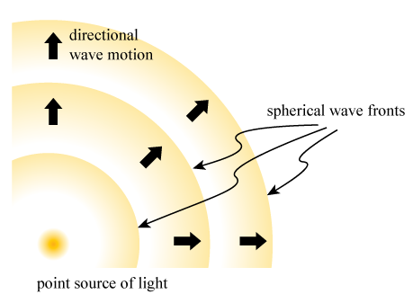
Figure 1
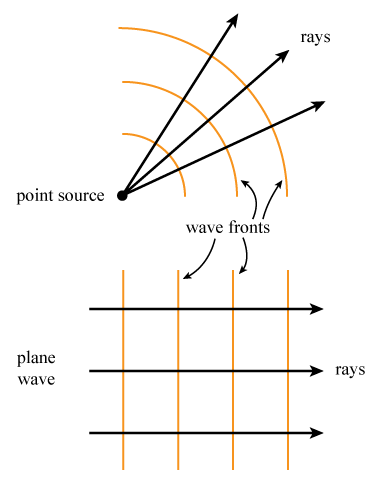
Figure 2
Index of Refraction
We can define a quantity called the index of refraction, n, of an optical media as the ratio of the speed of light in vacuum divided by the speed of light in the medium. Since nothing can go faster than the speed of light, including light, this ratio is always greater than or equal to 1. Light that has entered a material from vacuum will slow down in that material and we describe this light as having been refracted by this medium.The Laws of Reflection and Refraction
If we now investigate what happens to light that is incident on a surface between to different optical media, we find the following laws apply.-
1The incident, reflected, refracted rays and the normal to the surface all lie in the same plane.
-
2The angle of reflection as measured with respect to the normal to the surface is always equal to the angle of incidence, also measured with respect to the normal to the surface. This is true for all wavelengths of light and for any pair of materials that you may choose.
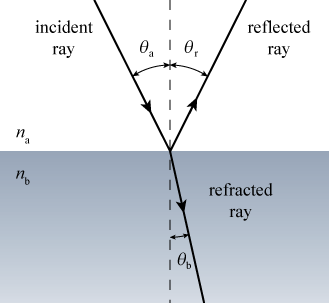
Figure 3
-
3For light of a single wavelength incident on this surface, we find that the ratio of the sines of the incident ray as measured to the normal divided by the refracted ray is equal to the inverse of the ratio of the indices of refraction for these two materials.
Objective
In this lab, you will use these basic principles of reflection and refraction to study several different simple optical systems. In each of these exercises, you will use a source of parallel light rays to study how they behave in these different configurations. The goal of this lab is to have you verify the above relationships.Apparatus
- Multi-ray light source
- Mounted mirror
- Concave/convex mirror
- Double-concave lens
- Masking tape
- Double-convex lens
- Plano-convex lens
- Prism
- Protractor
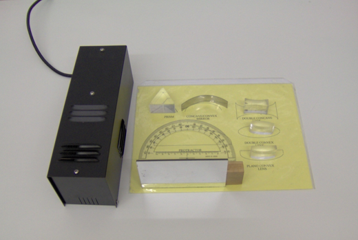
Figure 4
Procedure
Please print the worksheet for this lab. You will need this sheet to record your data.
Reflection from a Plane Surface
1
Set up the multi-ray light source to produce only one light ray. You may have to use masking tape to cover the extra slits. Set the small plane mirror in a vertical position in front of the light source on a sheet of paper. Position the face of the mirror perpendicular to the light ray and mark the position of the mirror and the path of the light ray on the paper.
The angle between the incident light ray (the light ray that shines on the mirror directly from the light source) and a line normal to the mirror is called the angle of incidence. The angle between the reflected light ray and the line normal to the mirror is called the angle of reflection. When the mirror is perpendicular to the incident light ray, the reflected light ray is directly along the path of the incident ray and thus the incident angle and the reflected angle are both equal to zero.
2
Rotate the plane mirror such that the incident angle is approximately 30° from the normal. Trace the incident and reflective lines on a sheet of paper and measure the angle of reflection with a protractor. Repeat this procedure with incident angles of 45° and 60°. See Figure 5.
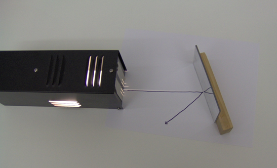
Figure 5
3
Remove the masking tape (if used) from the other slits on the light source and shine the light rays on the plane mirror. Trace the light rays and try to determine if the mirror image of an object is reversed. Explain your steps.
Concave and Convex Mirrors and Lenses
Reflection from a Concave Mirror
1
For this experiment, you will need three or more parallel light rays. The plano-convex lens (used to collimate the light rays) should now be placed in front of the slits of the multi-ray light source.
2
Place the concave mirror such that the light rays reflect back toward the light source and that the principal focus f of the mirror converges along the central ray (see Figure 6).
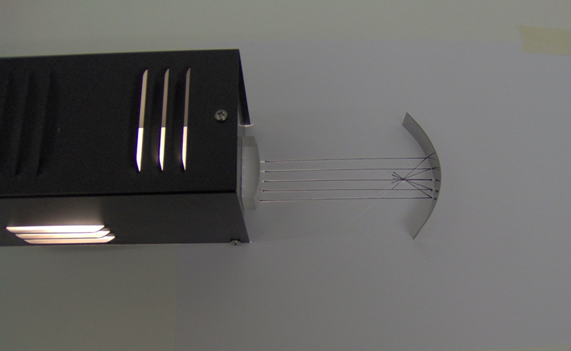
Figure 6
3
Trace the light rays on a sheet of paper (be sure to mark the location of the mirror).
4
Find the focal length of the mirror.
Reflection from a Convex Mirror
5
Turn the concave mirror around and use it as a convex mirror (see Figure 7).
6
Trace the light rays and find the focal length of the convex mirror. Again, be sure to mark the location of the mirror. Note that the focal point of this convex mirror cannot be observed directly. You may only determine this from the ray diagram.
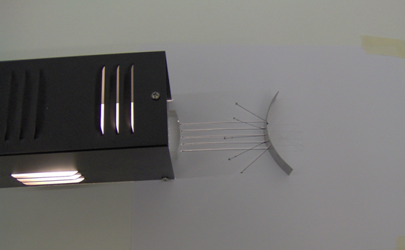
Figure 7
Refraction by a Convex Lens
7
Position the convex lens as shown in Figure 8.
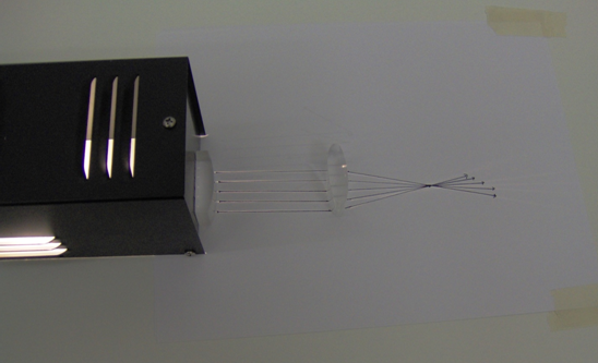
Figure 8
8
Find the focal length of the lens.
Refraction by a Concave Lens
9
Position the concave lens as shown in Figure 9.
10
Find the focal length of the lens by tracing the lines on a sheet of paper. Note that you must trace the diverging refracted light rays back to the focal point of the lens.
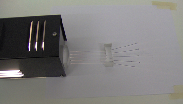
Figure 9
More Experiments with Concave–Convex Lenses
11
Position the lenses different distances and in different order from the light source and observe the various ray diagrams that are produced. An example is shown in Figure 10. Try others.
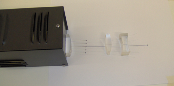
Figure 10
Reflection/Refraction by Prism
Angle of the Prism
1
Position the prism as shown in Figure 11. Adjust the light source such that two parallel rays are produced.
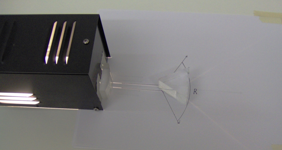
Figure 11
2
You will now measure the angle, R, of the prism.
-
aWhen the prism is positioned in the path of the light rays, a refracted ray and a reflected ray are produced.
-
bThe reflected ray will be used to find the angle, R.
-
cNote that the angle between the two reflected rays is equal to 2R. Why?
-
dDetermine R.
3
How does your measurement compare to a direct measurement of the angle of the prism?
Index of Refraction of the Prism
4
Adjust the light source so that only one light ray is produced. Position the light source and the prism as shown in Figure 12.
5
From your measurement of the angle of deviation, D, find the index of refraction of the prism.
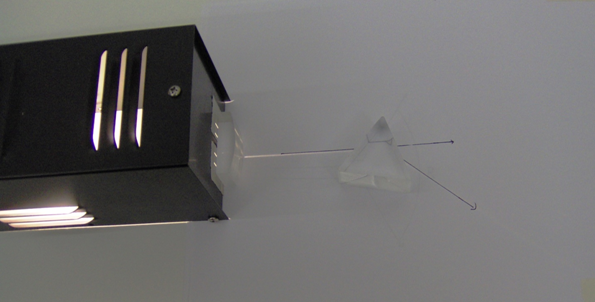
Figure 12
Total Internal Reflection
1
We will now investigate how the light is reflected and refracted if it is incident on the boundary between two materials from the side with the larger index of refraction. Take your light source and prism from the last setup and arrange the prism so that the light ray enters the prism and is aimed in order that it exits the prism on its longest side.
2
First arrange the light beam so that it is normally incident on this surface from inside the prism. What is the angle of refraction of the light as it leaves the prism?
3
Now begin to gradually rotate the prism in order that the angle of incidence inside the prism increases.
4
Pick an angle here and measure both the incident angle in the prism and the refracted angle in air and see if these angles are consistent with your earlier measurement of the index of refraction of the prism.
5
As you continue to gradually increase the angle of incidence for the light ray inside the prism, you should find an angle where there is NO refracted ray of light that leaves the prism. What is the value of this angle?
6
Is this consistent with Snell's Law and the value of the index of refraction that you measured earlier?
7
The angle where the rays are not able to exit the higher index material is called the critical angle. How does this angle depend on the indices of refraction of the two materials?