
Capacitors
Introduction
Overview
This lab is designed to study the phenomenon of charge storage, whose quantitative measure is known as capacitance. The initial two-plate capacitor was the Leyden jar, discovered in 1746. It puzzled the world until it was explained by Benjamin Franklin, using his electric fluid model and a dissectible capacitor (Franklin's version of the Leyden jar). You will perform the studies on a more precisely characterized capacitor, whose circular aluminum plates have a separation that can be varied. The capacitor plates will first receive a fixed charge. Then you will employ the multimeter to measure how the voltage changes when you vary the plate separation. Because the multimeter itself would discharge the capacitor, a special interface box (I.B.) has been designed, which draws off very little charge from the capacitor plates. From your measurements, you will be able to deduce the capacitance. Lastly, you will study the capacitance of the system using the multimeter to measure the capacitance. The multimeter determines the capacitance by measuring and interpreting the decay time of a signal that passes through a known resistance, R, internal to the multimeter and through the capacitance, C, to be measured. This decay time is proportional to RC. In a later lab, you will also measure capacitance in this way.Theory
Charge, Q, placed on a capacitor produces an electric potential, V (voltage) proportional to Q, with positive charge producing positive voltage. Thus we expect that the more charge, Q, that is removed from one conducting plate and given to another, the greater the voltage differenceΔV = V + − V −
between the two conductors. Moreover, the ratio of Q to ΔV should be independent of Q. This idea is incorporated in the definition of capacitance, C, for a system of two conductors:
Capacitance is so named because the more the charge, Q, for a fixed ΔV, the greater is the capacity of the object to store charge. Capacitance is measured in units of farads F, where 1 F is equal to 1 coulomb per volt, or F = C/V.
When conducting leads are attached to a capacitor plate, some charge flows onto the leads, thus effectively increasing the capacitance of the system. We call this sort of phenomenon, due to conducting leads, stray capacitance. Ordinary house wiring has a capacitance that is on the order of a picofarad (10–12 F) per foot. In the capacitance measurements we will perform in this lab, the effect of stray capacitance will have to be accounted for and subtracted out. The stray capacitance Cs is in parallel with the capacitance C under study, leading to a total capacitance
When the plates of a parallel plate capacitor are close to one another, the capacitance is given by
where εo = 8.85 × 10⁻¹² C2/N · m2
and κ is the dielectric constant of the material in the gap. Usually this dielectric material will be air, with κair ~ 1.
Objective
In this lab you will investigate the relationship between voltage, charge and plate separation for a simple parallel plate capacitor under different conditions.Apparatus
- 2 alligator clip leads
- DC power supply
- Circular parallel plate capacitor
- Multimeter
- Interface box (I.B.)
- Masking tape (on front lab table)
- Banana-banana leads
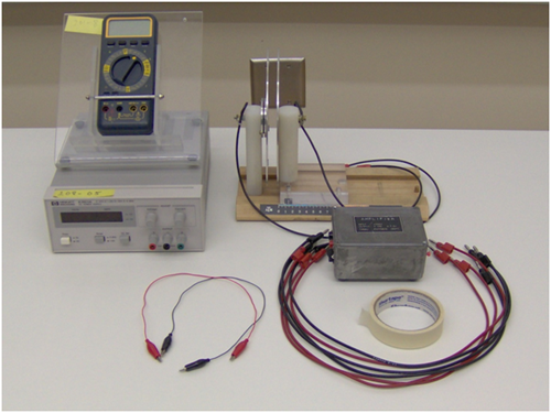
Figure 1
Procedure
Please print the worksheet for this lab. You will need this sheet to record your data.
NOTE: These measurements will be very sensitive to the humidity in the room and how you handle the apparatus during your measurements. To get the most reliable data you and your lab partners will need to plan on making the measurements as quickly as as you can. The best way to accomplish this is to have one of the team record the voltages measured, one member moving the capacitor plate and the third member watching to make sure that the other two members are not inadvertently touching the system leading to a discharging of the capacitor.
Voltage versus Inverse Distance (for fixed charge)
We will start our study of capacitors by showing how the voltage across the plates of a capacitor varies with plate separation, with fixed charge on the plates. For that purpose we will use a circular parallel plate capacitor whose plate separation we can control and measure. In order to make voltage measurements on the parallel plate capacitor, an interface box will be used in conjunction with the multimeter. Its purpose will be to detect the voltage difference across its input leads, and give an output voltage (with the help of the batteries inside this box) without draining the charge that produced the input voltage. It should be noted that the voltage reading of the multimeter will need to be multiplied by 100 since the interface box cuts the voltage output by 100.
Be sure to switch the interface box on/off switch to off when it is not in use.
1
Connect the input jacks of the interface box to the capacitor plates with the leads that are attached to the capacitor plates.
2
Now connect the multimeter to the output of the interface box. With the multimeter power off, set the multimeter to read volts, on either the 200 mV or 2 V scale. Connect the black (banana-banana) lead between the black output jack of the interface box and the COM jack of the multimeter. Connect the red (banana-banana) lead between the red output jack of the interface box and the V (voltage) jack of the multimeter.
3
Make sure that the power supply is turned off and the voltage knob is fully ccw. Connect the power supply to the capacitor plates using the banana-banana leads. Connect the black lead between the "–" jack of the power supply and the fixed plate of the parallel plate capacitor using one of the alligator clip wires to contact the capacitor. Connect the red lead between the "+" jack of the power supply and the movable plate of the parallel plate capacitor using the other alligator clip wire.
4
Your experimental setup should look like Figure 2. When you are sure your experimental setup is correct, turn on the multimeter, the power supply (which is set to 0 volts), and the interface box. Press the "zero push" button on the interface box to temporarily zero out the output signal. The multimeter should then read 0 V.
5
Set the power supply to produce 6 V across the capacitor plates. The multimeter should indicate about 0.06 V. This value should not depend on the capacitor plate separation (but start with a separation of about 2 mm). Without touching the plates, change the plate separation and see if the voltage changes. Charge can flow from the power supply to the plates (or vice versa) to maintain the voltage constant. Leave the plates about 2 mm apart.
6
The capacitor is now charged up. Disconnect the power supply alligator leads from the capacitor (do this as quickly as you can being careful not to discharge the charge on the capacitor). Now charge cannot flow from the power supply to the plates (or vice versa). Unless charge is drawn off in the air, or through the supports to the plates, or by the measuring device, the charge on each plate will not change. Vary the separation of the capacitor plates, starting when they are close and then increasing their separation, and note how the voltage varies with plate separation. Does the voltage increase and then reach some limiting value as the plates are farther separated? If not, then have your instructor check your experimental setup.
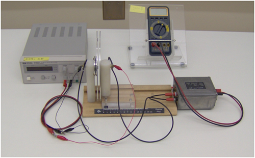
Figure 2
7
The distance scale on the capacitor may have an offset that may be different for each setup. Estimate and record the offset of the scale from a true reading. This will provide a correction that is most important at small distances. Note: WebAssign will assume your data has this offset value in subsequent calculations, so you must remember to add or subtract this offset when doing your calculations and curve fitting.
8
Construct a data table using Excel and record the voltage and plate separation. Don't forget to multiply your voltage readings by 100 as you fill in your data table. This should be done in 1 mm increments until 10 mm, then take measurements every 5 mm increment until about 50 mm separation. For each measurement, begin with a plate separation of 2 mm, connect the leads of the power supply, and set the plate voltage to 6 V. Disconnect the power supply from the plates and adjust the plate separation. Measure the plate voltage as a function of position for the range requested. Return to a plate separation of 2 mm and measure the voltage again. If it differs significantly from 6 V, see your instructor. (The interface box is not perfect, so it can drain off some charge, and therefore the voltage might decrease.) For each plate separation, take THREE sets of voltage measurements. Determine the average voltage for each plate separation (averaging the voltage actually helps remove some uncertainty in the plate separation).
9
Plot ΔV130/ΔV
vs. 1/(d − doffset)
using the scatter plot feature in Excel. (Don't forget to include the offset distance.) Is this relationship approximately true for some range of distances? Upload your graph from Excel to the lab report.
10
From your data, estimate Cs.
11
Derive Equation (4).
12
Turn off and disconnect the power supply and the interface box.
If the interface box is not turned off, the batteries inside it will run down!
Capacitance vs. Inverse Distance (using the multimeter)
In this part, you will examine how the capacitance of the parallel plate capacitor changes with plate separation using the multimeter's capacitance measuring option.1
Make sure the multimeter is off. Connect the two leads of the capacitor plates to the COM jack and the Cx jack of the multimeter. See Figure 3.
2
Set the multimeter dial to measure capacitance by rotating the dial's pointer to the F (Farad) scale of the multimeter. Since the capacitance in this experiment ranges from about 50-200 picofarad (pF, or 10–12 F), we will use the nanofarad (nF, or 10–9 F) range of the multimeter. Turn on the multimeter.
3
Vary the separation of the capacitor plates and using Excel, record the values of the measured capacitance as a function of the distance of separation between the plates. Does the capacitance decrease as the plates are further separated? If not, have your instructor check your experimental setup.
4
Using the data in your table, now make a graph of the capacitance of the system versus the 1/(d − doffset)
of the separation between the plates as before. Be sure to include any offset distance found earlier. Find the slope and intercept of this graph and using this information find the value of κεo for air. Does your measurement agree with the accepted value for this constant? Does the value for your intercept agree with the stray capacitance found in the previous set of measurements?
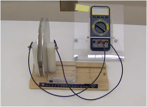
Figure 3