
Resistors in Series and Parallel
Introduction
Direct current (DC) circuits are characterized by the quantities current, voltage and resistance. Current is the rate of flow of charge. The SI unit is the ampere (A). By convention the direction of the current is the direction of flow of charge, even though in metallic conductors the current is due to flow of negative charge (electrons) in the opposite direction. Because of conservation of charge, the current is the same at all points in a single loop circuit. At a branch point in a circuit, where the conducting path splits into two or more paths, the total current into a branch point equals the total current out of that point. By convention, current flows out of the positive terminal of a battery or power supply and into the negative terminal. For current to be maintained in a circuit there must be a complete conducting path. Voltage is a measure of the electric potential difference between two points in a circuit. The SI unit is the volt (V). Since the electrical force is a conservative force, the sum of the voltage increases and decreases around any closed loop is zero. Resistance is the property of a circuit element (conductor) to oppose current flow. Resistance is defined by where V is the voltage across the circuit element and I is the current flowing through it. If R is constant, the same for all V, then the circuit element obeys Ohm's Law. The SI unit of resistance is the ohm (Ω). The resistance of a resistive circuit element changes with temperature. Two resistors R1 and R2 are connected in series if all the current that passes through R1 also passes through R2. Therefore, for two resistors in series the current I1 through R1 is the same as the current I2 through R2, and this current is the same as the current, I, that enters the series network:I = I1 = I2.
The total voltage, V, across the series network is the sum of the voltages V1 and V2 across each resistor. That is, V = V1 + V2.
The equivalent resistance, Rs, of R1 and R2 in series is given by
Two resistors R1 and R2 are connected in parallel if the voltages V1 and V2 across each are the same and equal to the voltage, V, across the parallel network. That is, V = V1 = V2.
The currents I1 and I2 through each of the resistors add to give the total current, I, flowing into and out of the network: I = I1 + I2.
The equivalent resistance Rp of R1 and R2 in parallel is given by
This can also be written as
Ammeters are used to measure current. An ammeter is connected in series with the circuit so that all the current being measured flows through the ammeter. Therefore, ammeters need to have very small resistance in order not to alter the current in the circuit. Voltmeters are used to measure voltages. A voltmeter is connected in parallel at the two points between which the potential difference is to be measured. Therefore, a voltmeter needs to have a large resistance so that very little current is diverted through it.
Objective
In this lab we will measure and analyze currents and voltages for circuits containing a single resistor and also for two resistors in series and for two in parallel.Apparatus
- 0-40 volt DC power supply
- 12 volt lightbulb and socket
- 150 and 700 ohm resistors
- Digital multimeter
Procedure
Please print the worksheet for this lab. You will need this sheet to record your data.
Measurement of Voltage
1
The power supply is a source of potential difference (voltage). Locate the DC power supply at your table.
Press the POWER ON/OFF button to the ON position. Next, press the RANGE button to the IN (0.85 A) position. This sets the power supply to the 0-35 V/0-0.85 A range.
Rotate the voltage and current ADJUST knob counterclockwise. Then set the maximum output current for this experiment by pressing the CC Set button, and while holding it down rotate the current ADJUST knob clockwise until the AMPS display reads 0.30 A. Release the CC Set button. Do not move the current setting knob (CC Set) at any point during the experiment.
2
The multimeter is a measuring device that is used to measure voltage differences, electrical currents, and electrical resistances. It can measure other electrical properties as well. See Figure 1. At the top of the meter is an LCD (liquid crystal display), in the middle is the Function/Range Switch (dial), and at the bottom are four input sockets.
Note: The meter is particularly sensitive (and prone to blowing a fuse) when using the 200 mA Input Jack (see I in the key for Figure 1.)
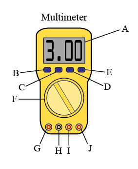
Figure 1
Key for Figure 1:
-
A3-1/2 digit LCD with annunciators.
-
BON/OFF button: Turns power to meter on and off.
-
CHI/LO button: Selects high or low trigger level for frequency measurements.
-
DMAX button: Selects maximum reading hold function.
-
EDC/AC button: Selects DC or AC type voltage.
-
FFunction/range switch: Selects the function and range desired.
-
GV Ω Input Jack: Input connector for volts, ohms, diode test, continuity, frequency and logic.
-
HCOM Input Jack: Ground input connector.
-
I200 mA Input Jack: Input connector for current up to 200 mA, Lx (Inductance), Cx (Capacitance).
-
J10 A Input Jack: Input connector for current to 10 A.
To measure a given quantity, the dial must be at the appropriate setting and the appropriate two input jacks must be employed. Thus, when turning the dial to change from one type of measurement to another (e.g. from voltage difference to electric current), you may have to change input sockets as well. If overloaded, the fuse can blow out.
Caution:
To protect itself, the meter buzzes when overloaded; if it buzzes, immediately disconnect the meter leads!
To protect itself, the meter buzzes when overloaded; if it buzzes, immediately disconnect the meter leads!
To protect the meter from overload when an unknown voltage or current is measured, the meter should first be set to the highest scale for that function. If the reading then is not large enough to give at least three significant figures, the scale should be switched (if possible) to one that permits an accurate measurement.
3
To turn on the multimeter, toggle the top left button on the meter until there is a display on the meter face. To set up the multimeter to measure DC voltages, V, toggle the top right button to DC. Be sure that the meter display reads DC.
Turn the Function/Range Switch to the voltage (V) range and dial the setting to 20. The meter is now set to read voltages up to 20 volts DC.
Attach banana to banana leads to the common (COM) jack and to the voltage (V) jack.
4
Connect the multimeter leads to the + and – terminals of the power supply. See Figure 2. On the power supply, rotate the voltage ADJUST knob clockwise until the volts display reads 5.0 volts. Compare the voltage readings on the multimeter and on the power supply's meter. These two readings may not be exactly the same. The multimeter is expected to be more accurate.
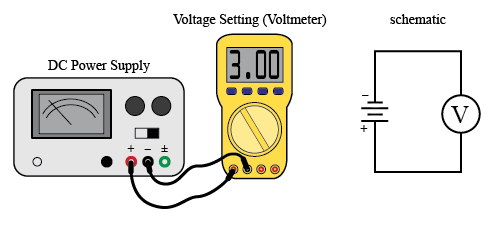
Figure 2
Current and Voltage for a Single Resistor
1
Turn down the voltage of the power supply (counterclockwise) to zero volts. Connect the power supply to the resistor on the circuit board that is marked 700 ohms. (Do not readjust or change the current setting on the power supply.) We will use the multimeter to measure the DC current through the 700-ohm resistor as a function of the applied voltage. To do this, we must connect the multimeter in series with the resistor, so that the same current passes through both. Since it is easy to blow a fuse when the multimeter is on its current setting, follow the instructions carefully.
Set the multimeter dial to the 20 mA current scale and connect the banana plugs to the COM and mA jacks on the meter.
Caution:
Do not turn up the voltage on the power supply until your TA checks your circuit.
Do not turn up the voltage on the power supply until your TA checks your circuit.
2
After being given the go-ahead by your TA, set the power supply to 1 volt and record in Table 1 the current through the resistor as indicated on the multimeter. Repeat with the power supply set to 2, 3, 4, and 5 volts.
3
Use Excel to plot your data, with current on the vertical axis and voltage on the horizontal axis. Refer to the Appendix in the online lab manual for instructions on graphing with Excel. If you get the results that are expected, the data will fall close to a straight line that passes through the origin. Use Excel to find the slope of the straight line that best fits your data and record your result, including units.
4
Use Ohm's law and the slope from your graph to calculate the resistance, R, of the resistor, in units of ohms (Ω). Record your result.
Current and Voltage for a Light Bulb
1
TURN THE POWER SUPPLY VOLTAGE TO ZERO but do not turn off the power supply. Do not readjust the current setting on the power supply (CC Set). We will use the multimeter to measure the DC current through the light bulb as a function of the applied voltage. To do this, we must connect the multimeter in series with the light bulb, so that the same current passes through both. Since it is easy to blow a fuse when the multimeter is on its current setting, follow the instructions carefully.
2
Set the multimeter dial to the 10 A DC current scale. Use the COM and 10 A input jacks. Connect the circuit as shown in Figure 3.
Caution:
Do not turn up the voltage on the power supply until your TA checks your circuit.
Do not turn up the voltage on the power supply until your TA checks your circuit.
3
After being given the go-ahead by your TA, turn the power supply voltage to 2 volts. In Table 2 record the current reading on the multimeter. Repeat for power supply voltages of 4, 6, 8, 10, and 12 volts.
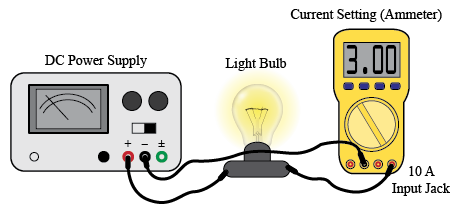
Figure 3
4
Use Excel to plot your data, with current on the vertical axis and voltage on the horizontal axis. It is expected that your data will not fall close to a straight line. Define R =
and calculate R for each set of V and I values in Table 2 and record in the third column of Table 2.
Does R increase, decrease, or stay the same as the current, I, through the light bulb increases?
| V |
| I |
Two Resistors in Series
1
Connect the two resistors on the circuit board that are marked 150 ohm and 700 ohm as shown in Figure 4. They are said to be in series because all the current that passes through one also passes through the other. Make sure the power supply voltage is set to zero. Connect the power supply to the series resistor combination as in Figure 4. Set the power supply to 5 volts. Set the multimeter dial to the 20 V range and use the COM and V jacks. With the multimeter, measure and record the potential differences (voltage) V150 and V700 across each resistor and the voltage, V, across the two-resistor combination.
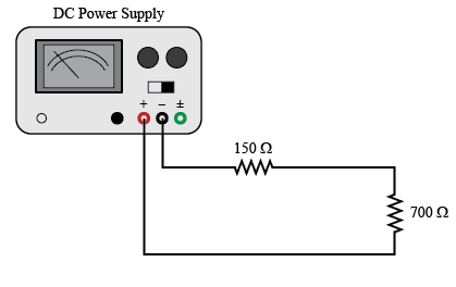
Figure 4
2
When you have completed these measurements, set the power supply voltage to zero and disconnect the multimeter from the circuit. Which of the following better represents your results?
-
•V = V150 + V700
-
•V = V150 = V700
3
With the power supply voltage set to zero, connect the multimeter in series with the resistors as shown in Figure 5. Set the multimeter to the 200 mA DC current range and connect the multimeter leads to the correct jacks.
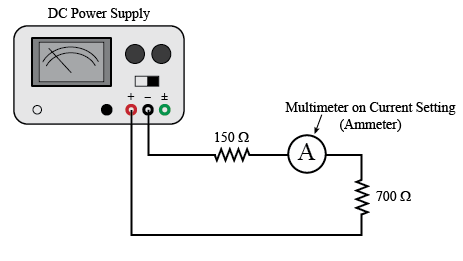
Figure 5
Caution:
Before proceeding, have your lab instructor check that you have the correct setup: a fuse may blow if the meter is not connected to the proper points in the circuit.
Before proceeding, have your lab instructor check that you have the correct setup: a fuse may blow if the meter is not connected to the proper points in the circuit.
After being given the go-ahead by your TA, turn on the power supply and set it to 5 volts. Measure the current in the wire between the two resistors, the wire between the 700 ohm resistor and the power supply and the wire between the 150 ohm resistor and the power supply. Verify that these three currents are equal.
4
Continuing with the circuit shown in Figure 5, set the power supply voltage to 2 volts. In Table 3 record the current reading on the multimeter. Repeat for power supply voltages of 4, 6, 8, 10, and 12 volts.
5
Use Excel to plot your data, with current on the vertical axis and voltage on the horizontal axis. Use Excel to find the slope of the straight line that best fits your data and record your result, including units.
6
Use Ohm's law and the slope from your graph to calculate the equivalent resistance, Rs, of the two resistors in series, in units of ohms (Ω). Record your result.
Two Resistors in Parallel
1
Connect the two resistors on the circuit board that are marked 150 ohms and 700 ohms as shown in Figure 6a. They are said to be in parallel since the voltage across each resistor equals the voltage of the power supply and the resistors provide parallel paths for the current flow.
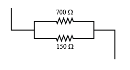
Figure 6
2
Make sure the power supply voltage is set to zero. Connect the power supply to the parallel resistor combination as in Figure 6b. Set the power supply to 5 volts. With the multimeter, measure and record the currents I150 and I700 flowing through each resistor and the total current, I, flowing through the power supply.
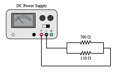
Figure 7
3
When you have completed these measurements, set the power supply voltage to zero and disconnect the multimeter from the circuit.
4
Which of the following better represents your results?
-
•I = I150 + I700
-
•I = I150 = I700
5
Continue with the parallel resistor network. With the power supply voltage set to zero, connect the multimeter to measure the total current, I, flowing through the power supply. Set the multimeter to the 200 mA DC current range.
Caution:
Before proceeding, have your lab instructor check that you have the correct setup: a fuse may blow if the meter is not connected to the proper points in the circuit.
Before proceeding, have your lab instructor check that you have the correct setup: a fuse may blow if the meter is not connected to the proper points in the circuit.
After being given the go-ahead by your TA, turn on the power supply and set it to 2 volts.
6
In Table 4 record the current reading on the multimeter. Repeat for power supply voltages of 4, 6, 8, 10, and 12 volts.
7
Use Excel to plot your data, with current on the vertical axis and voltage on the horizontal axis. Use Excel to find the slope of the straight line that best fits your data and record your result, including units.
8
Use Ohm's law and the slope from your graph to calculate the equivalent resistance, Rp, of the two resistors in parallel, in units of ohms (Ω). Record your result.