
Magnetic Fields and Forces
Introduction
Currents
Moving charges produce a magnetic field. Therefore, since current in a wire is due to moving charges, a current in a wire produces a magnetic field. For a long, straight wire carrying current I, the magnetic field a distance r from the wire is given by where μ0 is a constant. In SI units, μ0 = 4π x 10–7 T · m/A. The magnetic field lines are closed circles that encircle the wire. The direction of the magnetic field lines around a straight wire are given by a right-hand rule: Grasp the wire with your right hand with your thumb extended in the direction of the current. Your fingers then curl around the wire in the direction of the magnetic field lines. For example, for the straight wire shown in Figure 1, with the current toward the right, the magnetic field at points above the wire is directed out of the page and the field at points below the wire is directed into the page.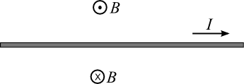
Figure 1
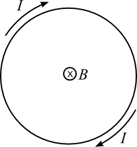
Figure 2
n =
is the turns per unit length. This equation shows that the magnetic field inside the solenoid is proportional to the current. The magnetic field of the solenoid is the superposition of the fields due to each turn so the direction of the magnetic field inside the solenoid is given as follows: Grasp the solenoid with the fingers of your right hand curling around the solenoid in the direction of the current. Your extended thumb then points in the direction of the magnetic field. Outside the solenoid the field is small, especially away from the ends of the solenoid.
| N |
| L |
Magnetic Materials
In ferromagnetic materials (like iron, for example) the current loops due to the orbiting electrons in the atoms produce magnetic fields. These magnetic fields line up parallel to each other in regions called magnetic domains. When there is no externally applied field, the orientations of the fields of the domains are random and the net magnetic field produced by the piece of metal is zero. But when an externally applied field is present, the domains with magnetic field in the direction of the external field grow in size and the net magnetic field is in the direction of the external field but is much larger than the external field. Some magnetic materials retain their magnetization after the external field is removed and can be used to make permanent magnets.Compass Needles
By convention, the magnetic field of a permanent magnet, for example a bar magnet, is directed away from the north (N) pole of the magnet and toward the south (S) pole. The geographical North Pole of the Earth is a magnetic south pole. The end of a compass needle that points toward geographical north is, therefore, pointing in the direction of the magnetic field. Compass needles can, therefore, be used to determine the direction of the magnetic field produced by a configuration of current carrying wire, for example by a solenoid.Objective
In this lab, we will determine the direction of the magnetic field at the ends of a solenoid wrapped on an iron core and compare the results to the predictions of the right-hand rule. The dependence of the magnetic field on the magnitude of the current in the solenoid will be explored qualitatively.Apparatus
- Electromagnet (long rod with wire winding on it)
- DC power supply
- Iron filings (in a plastic tray)
- Compass
- Two connecting wires with banana plugs
Procedure
Please print the worksheet for this lab. You will need this sheet to record your data.
Electromagnet
1
Locate the DC power supply on your lab table but do not connect it to the circuit yet.
Press the On/Off power button to the On position. Next, press the Range button to the "in" position (this sets the power supply to the 0-35 V/0-0.85 A range). Rotate the Voltage and Current ADJUST knobs fully counterclockwise. Then set the maximum output current for this experiment by pressing the CC Set button, and while holding it down, rotate the Current ADJUST knob clockwise until the AMPS display reads 0.80. Release the CC Set button. Do not move the Current setting knob after this adjustment is done. The Voltage ADJUST knob will be used to set the output voltage but at this point leave the output at zero volts.
2
Connect the electromagnet to the DC power supply. Note the polarity of the power supply (which wire of the electromagnet is connected to the + terminal) and use that to determine the direction of the current in the solenoid. Use the right-hand rule to determine the expected direction of the magnetic field at each end of your electromagnet. Record this information by choosing "toward" or "away" in each blank.
3
Turn up the voltage until you get a current of 0.80 A. Use a compass to measure the direction of the magnetic field at the ends of the electromagnet, and record your results by choosing "toward" or "away" in each blank.
If your measured results do not agree with your predictions from the right-hand rule, discuss with your lab partner what is wrong with your application of the right-hand rule and correct it. If you and your lab partner can't figure out what you are doing wrong, discuss it with your TA.
4
Set the voltage back to zero and reverse the leads to the power supply. Repeat steps 2 and 3.
5
Check that the current is still set to 0.80 amps and pick up as many iron filings as possible using only the end of the rod. Turn off the power supply. Note what happens to the iron filings. Is the rod permanently magnetized?
6
Remove any iron filings remaining on the rod. Increase the voltage to produce a current of 0.80 amp and pick up as many iron filings as possible with the end of the rod. Release them onto a piece of paper by turning off the power supply. Set the voltage to give a current of 0.40 amp and repeat, dropping the iron filings at a different place on the paper. How do the sizes of the two piles compare? Does the strength of the electromagnet depend on the magnitude of the current?
Return the iron filings to the holder and turn off the power supply and disconnect the connecting wires so that you leave the equipment just as it was at the start of the lab.