
HOW TO USE INSTRUMENTS
Analytical Balance
The object to weigh must be clean and dry on the bottom, and it must be at or near room temperature. Do not weigh anything that is warm or hot. Once you have chosen a balance to use, record the balance number and use only that balance for that day's lab. If the balance and nearby table are not already clean, clean them off. Close the doors on the balance. Zero the balance. Open a door and gently set the object being weighed on the balance pan. Close the door. Record the mass of the object to the nearest 0.0001 g. As with every measurement, also record the uncertainty in your reading. Open the door, carefully remove the object, and close the door again. Leave the balance and nearby table clean.The Barometer
The barometer is the instrument with which people read atmospheric pressure. The force of the air pressing down on a reservoir of liquid mercury drives the mercury up into an evacuated tube. The air pressure is directly observed by the height of the mercury column. Below is the procedure for reading the barometer.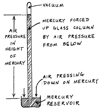
Figure 1: Barometer
1
The mercury reservoir at the bottom of the barometer should have been lowered by the previous user so it does not touch the white cone. If it is touching that cone, lower it, carefully raise it until the mercury surface just touches the tip of the cone.
2
Raise the readout device at the top of the barometer, then carefully lower it until it is just aligned with the top of the mercury meniscus.
3
Read the height of the mercury column, using the vernier scale.
4
Repeat this procedure to get the reproducibility.
5
When you are finished, raise the readout well above the top of the mercury column and lower the mercury reservoir in preparation for the next person.
6
If you have raised or removed your goggles to read the barometer, replace them over your eyes before you return to the lab!!!
Bunsen Burner
Caution:
Burners make things hot! Burners themselves are hot! When you use a burner, remember what you have heated; don't touch what you have heated.
Burners make things hot! Burners themselves are hot! When you use a burner, remember what you have heated; don't touch what you have heated.
- Make sure that there is nothing flammable within 5 feet of your burner.
- All organic solvents are highly flammable.
- Loose human hair is highly flammable.
- You may heat pyrex beakers, test tubes, and flasks.
- Never heat volumetric glassware such as graduated cylinders or volumetric flasks.
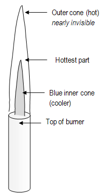
Figure 2: Bunsen Burner Flame
- Never leave a flame unattended, so turn off your burner if you have to leave your work bench.
- If you are heating a test tube, hold it with a test tube clamp.
- If you are heating a test tube, point it away from people (boiling material could fly out).
- Heat test tubes gently, in cool part of flame.
- Heat test tubes over whole extent of contents, not over one spot at bottom.
- Never heat a test tube while pointing it at someone!
pH Meter
One of the common measurements in a chemistry lab is of the pH of a solution using the pH meter. This instrument employs electrodes that measure the voltage in the concentration cell formed by the solution whose pH is being measured and a reference electrode.- Treat the electrode of the pH meter gently. It is delicate and expensive.
- Whenever you are not using it, immediately immerse the electrode in water or buffer, according to the manufacturer's instructions.
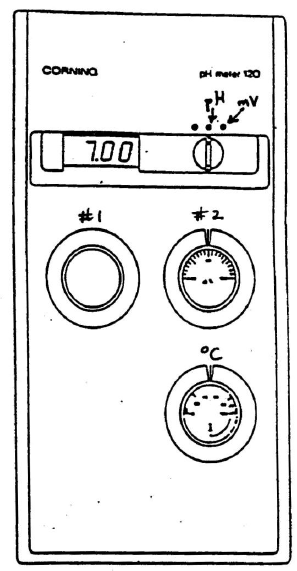
Figure 3: pH meter
Calibrating the pH Meter:
You must calibrate the pH meter before use. Please follow the exact instructions that are written on the card by your specific pH meter. The following instructions are either the same or similar to what you will need to do.1
Set the temperature control knob to the appropriate temperature, usually that of the room.
2
Be sure the meter is turned off. Set calibration knob #2 to 100%. Remove the electrode from the water or buffer it is stored in and wash it with deionized water from a wash bottle. Gently touch its tip with a Kimwipe to remove the water.
3
Place the electrode in a reference buffer solution of pH 7 and turn the meter to pH. Use calibration knob #1 to adjust the pH reading to 7.00.
4
Rinse the electrode and place it into a second reference solution chosen so the pH values you are planning to measure lie between 7.0 and the pH of the second reference buffer. Use calibration knob #2 to set the display to the value of the second buffer.
Determining the pH of a Solution:
1
Rinse the electrode with deionized water into a waste beaker.
2
Immerse the electrode in the unknown solution and turn the meter to pH. Allow time for the display to stabilize and record the reading.
3
Rinse the electrode with deionized water between solutions.
4
Periodically recalibrate the meter, especially after you have completed a titration.
5
When you are done with the electrode, rinse it with deionized water and return it to its storage solution.
Note: These are very general instructions. Each brand of pH meter has its own instructions, which you should always read and follow.
Hydrogen and Helium Emission Lamps
Please do not leave the lamps on for the entire lab period. Turn them off when not in use. Do not touch any part of the lamp.Caution:
These lamps are high voltage.
These lamps are high voltage.
Use of the Spec 20 Spectrometer
A spectrophotometer is an instrument used to measure the light absorption (transmittance). A bulb emits white light (contains all wavelengths). This light passes through a monochrometer, which is a device (usually a prism or a grating) that spreads out the different colors and lets only one through. By adjusting the monochrometer, the wavelength selected can be changed. This single color (identified by its wavelength) of light is then passed through the sample. The light then strikes a detector, which is a photocell, a device whose electrical output is proportional to the amount of light that strikes it. This output is amplified to drive a meter that shows how much light was absorbed or transmitted. We use a Bausch and Lomb Spectronic 20 (often called simply a "Spec 20"). The detectors used in the Spec 20 are sensitive to only limited ranges of wavelengths. The blue-sensitive detector is used for the range 350-595 nm, and the red-sensitive detector is used for the range 600-950 nm. Be sure you set the instrument for the detector that will work for the wavelength you are measuring. Spectrometers read the transmittance T (the fraction of the entering light transmitted):( 1 )
Transmittance = T = fraction of entering light transmitted =
=
| intensity of light leaving cell |
| intensity of light entering cell |
| I |
| I0 |
( 2 )
A = log T = εbc,
- These quantities are explained in detail in Lab 9.
A = log T = εbc,
Steps for Using Spec 20 to Measure Absorbance:
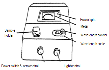
Figure 4: Spec 20
- Warnings:
- Do not fill the cuvet more than 2/3 full.
- Be sure the cuvet is dry before you put it into the sample holder.
- Do not handle the sides with your fingers.
- Make sure the mark on the cuvet lines up with the mark on the cell holder (this insures a constant path length for all readings).
- Do not leave a cuvet in the sample holder when you have finished a reading.
- Make sure the sample holder is empty and close the sample holder cover when you are done.
1
If the instrument is off, turn it on. Be sure the sample holder is empty and close the cover. Let the spec warm up for at least 30 min. Your instrument should already be on and warmed up.
2
Set the wavelength that you want, and be sure you are using the detector (blue-sensitive, 350-595 nm, or red-sensitive, 600-950 nm) appropriate to that wavelength.
3
Blank the spec – do not just do this once, but every time you change the wavelength setting on the instrument.
Adjust 0% transmittance: With the sample holder empty and the cover closed, turn the zero control knob to give a 0% T reading on the meter. A shutter covers the light source when no cuvette is in the cell holder, so the detector should not be detecting any light (i.e., no transmittance).
Adjust 100% transmittance: Insert the cuvet containing the reference solution (usually pure solvent, called a "blank"). Close the cover. Turn the light control knob to give a 100% T reading. (If the needle flickers or wanders after about 5 sec, report the malfunction.) Remove the cuvet and close the cover.
Re-check 0% transmittance: Step 4 can shift what you did in Step 3, so perform step 3 again. If you must re-adjust the zero control knob, then you must repeat step 4. Cycle between steps 3 and 4 until no further changes are needed.
4
Measure %T (or absorbance) of the sample.
Rinse the cuvet and add the sample. Insert the cuvet and close the sample cover. Read percent transmittance.
5
Remove the cuvet and close the cover.
Calipers (Vernier Scale)
A vernier scale is a device that permits accurately making a reading that lies part way between two values on an instrument such as a barometer or a set of calipers. A vernier consists of a small, movable auxiliary scale, marked from 0 to 10, attached parallel to the main scale of the instrument, and occupying exactly 9 values on the main scale.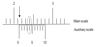
Figure 5: Example measurement
1
Locate the 0 mark on the auxiliary scale and notice where it falls on the main scale (the arrow in the figure). Read the position of this mark. In this case, the 0 mark is above 2.1 and below 2.2. You now have two significant figures, but the third is still unknown (2.1something).
2
Find which mark (0 to 9) on the auxiliary scale lines up directly across from a mark on the main scale (circled in the figure). This mark on the auxiliary scale is the last significant figure of your measurement (here, 2.14).
3
The uncertainty in your measurement will be plus or minus one in the significant figure provided by the auxiliary scale(barometer ± 0.1 mm, calipers ± 0.01 cm).
You should check how reproducibly you can perform repeated measurements with the instrument.
4
Many vernier instruments are calibrated in two different units, just as a ruler may be calibrated in inches on one side and centimeters on the other. Be sure to use the proper scale (metric in lab).
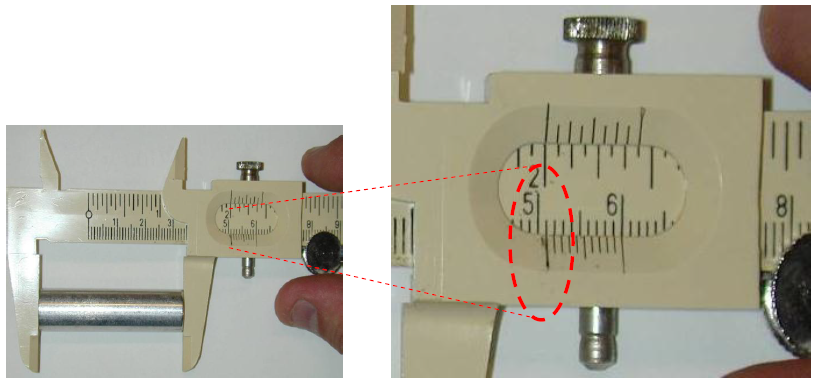
Figure 6: Measuring length of cylinder
Use Of The Voltmeter
Never immerse the clips at the ends of the leads in any solution. Always make sure the clips make good connection with the metals. The digital voltmeter, shown in the figure, should have the red wire plug in the upper (+) hole labeled VΩ, and the black lead in the lower terminal hole labeled COM.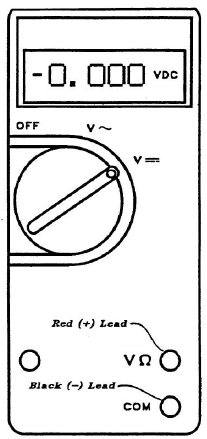
Figure 7: Voltmeter
1
Check that the alligator clips on the ends of the leads are not corroded. If they are, sandpaper them lightly.
2
Turn the voltmeter on.
For direct current, use the setting labeled as V 3
The voltmeter is sensitive. You may get what look like large fluctuations in voltage. Please do the best that you can – wait for a few seconds and take your best guess at the reading. Read the voltmeter to 0.001 V, and estimate your uncertainty.
4
Turn the voltmeter off when it is not in use. Please clean the clips if needed.
-
aThe size or magnitude of the voltage, given on the display
-
bWhich lead is the positive and which is the negative
- If a minus sign (shown in figure 7) does not appear, the plus voltage means the red wire is positive and the black is negative.
- If the minus sign appears, the negative voltage means the red wire is negative and the black positive. Thus, the sign in front of the display tells you the polarity of the red lead, as compared with the black lead.