
Ohm's Law and Electrical Circuits
Introduction
In this experiment, you will measure the current-voltage characteristics of a resistor and check to see if the resistor satisfies Ohm's law. In the process you will learn how to use the multimeter to measure voltage, current, and resistance. You will then test some of the laws of circuit theory. When a potential difference, V, is applied across a conductor, an electrical current, I, will flow from the high potential end to the low potential end. In general the current will increase with the applied voltage (potential difference). A plot of the current as a function of the voltage is called the current-voltage (I-V) characteristic. If the I-V characteristic is a straight line, as in Fig. 1, then we say that the piece of conductor satisfies Ohm's law: V = IR, where R is a constant defined to be the resistance and has units of volts/ampere, or Ω (ohm).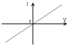
Figure 1: I-V curve for an ohmic material
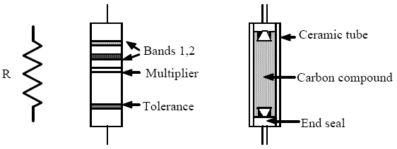
Figure 2
-
1Kirchhoff's Loop Rule
- The total change in the voltage around any closed loop is zero. This is obvious when you consider that voltage is a difference of potential. This rule just says that the difference of potential from one point to that same point is zero, no matter how you go around the circuit.
-
2Kirchhoff's Junction Rule
- The amount of current flowing into any point on a wire (or into a junction of wires) is always equal to the amount of current flowing out of it.
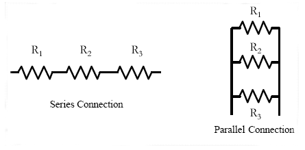
Figure 3
( 1 )
R = R1 + R2 + R3 (resistors in series)
( 2 )
| 1 |
| R |
| 1 |
| R1 |
| 1 |
| R2 |
| 1 |
| R3 |
Apparatus
The apparatus for this experiment consists of a regulated power supply and two multi-meters. These pieces of equipment are described below.Regulated Power Supply
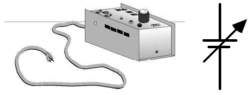
Figure 4
Measuring Currents, Voltages, and Resistances
When the multi-meter is set to measure current it serves as an ammeter, when it is set to measure voltages, it serves as a voltmeter, and when it is set to measure resistances, it serves as an ohmmeter. The symbols for the ammeter, voltmeter and the ohmmeter are given below.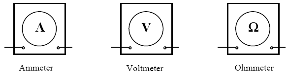
Figure 5
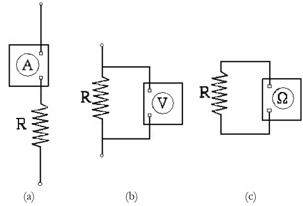
Figure 6
Making Simultaneous Current and Voltage Measurements
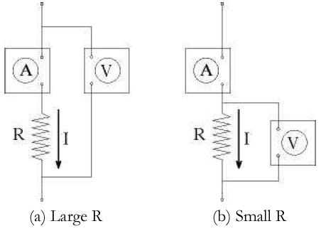
Figure 7
IRA / IR = 0.001/1000 or 0.0001%.
The method illustrated in Fig. 7a should therefore be used to measure large resistances.
In Fig. 7b, the voltmeter measures the voltage across the resistor R, but the ammeter does not
measure the current through the resistor, I. Instead it measures the current through the resistor plus the
current through the voltmeter, IV. The sum of these currents is given by:
( 3 )
I + IV =
+
| VR |
| R |
| VR |
| RV |
R/RV = 0.1/100,000 or 0.0001%.
The method illustrated in Fig. 7b should be therefore be used to measure small resistances.
Procedure
Resistance Measurements
-
1Using the multimeter as an ohmmeter, measure and record the resistances of each of the three resistors provided. Remember to include uncertainty estimates based on the accuracy of the meter.
-
2Connect the three resistors in series. Record the equivalent resistance determined with the ohmmeter.
-
3Connect the three resistors in parallel. Record the equivalent resistance determined with the ohmmeter.
Current-Voltage Characteristics of a Resistor
This part of the experiment requires you to simultaneously measure the current and voltage on a resistor. The resistors used in this experiment have resistances of about 1000 Ω. Therefore, the method shown in Fig. 7a should be used to simultaneously measure I and V.-
1Select the resistor with about a 600 Ω resistance. Connect the power supply (do not turn it on yet), the voltmeter, the ammeter, and the resistor according to the circuit diagram shown in Fig. 7a. You may use the Fluke 77 as an ammeter and the Micronta as a voltmeter. Since the voltage of the power supply is about 10 V, the current will be of the order of milliamperes. Thus the "300 mA" and the "COM" terminals on the Fluke 77 should be used for the ammeter connection.
-
2Have your lab instructor check your circuit before you turn on the power supply.
-
3With the control knob at the minimum setting (fully counterclockwise), turn your power supply on. Turn the control knob up until the voltmeter reads about one volt. Record the current and the voltage.
-
4Increase the voltage in steps of 2 V. Measure and record the current and the voltage. Stop when the voltage reaches about 15 Volts.
-
5Turn the control knob on the power supply fully counterclockwise and turn the power switch off.
-
6Check your data by making a rough plot of V vs. I on the data sheet or a piece of graph paper. Check if your plot agrees with Ohm's Law. Check if the slope of your plot gives the correct resistance.
-
7Repeat the above steps to measure the V vs. I characteristics of a light bulb (#53, 120 mA at 14 V). Use the same circuit but replace the resistor with the light bulb. Take data readings in current steps of 10 mA up to a maximum of 100 mA.
Kirchhoff's Rules
In this experiment you will verify Kirchhoff's rules on a simple circuit shown below.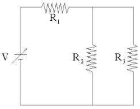
Figure 8
-
1Connect the three resistors and the power supply according to the circuit diagram above. Be sure to identify and record the values of the three resistors.
-
2Have your lab instructor check your circuit before you turn on the power supply.
-
3Turn on the power supply and adjust the control knob until the power supply voltage is about 10 V. Record the output voltage V and keep it fixed for the remaining experiment.
-
4Measure and record the voltages V1, V2, and V3 across each of the resistors. Remember to include uncertainty estimates for each of your measurements based on the accuracy rating of the meter.
-
5Measure and record the currents I1, I2, and I3 through each of the resistors, along with appropriate uncertainty values. Because the power supply is always on for this measurement, it is easy to blow the fuse on your multimeter if it is not connected properly. Turn off the multimeter when you are making the connection. Make sure that the multimeter is in series with the resistor you are measuring before turning it on. If you are not sure, check with your instructor.
-
6Turn off the multi-meter and the power supply when you are finished with the experiment.
When you are finished with the experiment, please clean up your work area and return all the
wires and clips to their storage bins.
Be sure that you and your instructor initial your data sheet(s), and that you hand in a copy of
your data before you leave the lab.
Data Analysis
Resistance Measurements
For this part we shall denote the calculated equivalent resistance by RT, and the measured equivalent resistance by R.-
1Calculate the sum RT of the resistances for the three resistors R1, R2, and R3 connected in series.
-
2What are the uncertaintiesuR1, uR2, uR3in your measurements of the resistances? What is the source of the uncertainty?
-
3Using your values for the uncertainties of the three resistors, calculate the uncertainty of the sum uRT by using the propagation of uncertainty formula for the sum.
-
4Summarize your values of R and RT, including uncertainties.
-
5Calculate the total resistanceRTfor the parallel connection.
-
6Using the propagation of uncertainty formula for a ratio, show that the fractional uncertainty of f is the same as the fractional uncertainty of 1/f, i.e. show
=uf f
.u1/f 1/f -
7Using the equation in step 6, calculate the uncertainties of 1/R1, 1/R2 and 1/R3. Then, using the propagation of uncertainty for the sum, calculate the uncertainty of 1/RT from the uncertainties of 1/R1, 1/R2 and 1/R3. Finally, again using the equation in step 6, calculate the uncertainty of RT from the uncertainty of 1/RT.
-
8Summarize your values of R and RT, including uncertainties.
Current Voltage Characteristics of a Resistor and a Light Bulb
-
1Prepare two tables (one for the resistor and one for the light bulb) of currents and the voltages from the data obtained.
-
2Make a scatter-plot of V vs. I for the resistor data.
-
3Generate a least-square linear fit of your plot to Ohm's law: V = IR. What do the slope and intercept parameters in the fit correspond to?
-
4Summarize the value of R (measured by a multimeter) and the fitted value of R, including uncertainties.
-
5Make a scatter-plot of V vs. I for the light bulb data.
Kirchhoff's Loop and Junction Rules
-
1What are the uncertainties in your measurements of the currents I1, I2, and I3? Based on these uncertainties, check if the currents you measured satisfy the junction rule, i.e.I1 = I2 + I3.
-
2There are three loops in the circuit used in this part. Write down the equation given by the loop rule for each loop. Based on the uncertainties in your measurements of V1, V2, and V3, verify that the voltages you measured satisfy the equations derived from the loop rule.