
Thin Lenses and Lens Systems
Introduction
When light from an object passes through a lens, an image of the object is generally formed. The distance, q, of the image from the lens is determined by the focal length, f, of the lens and the distance, p, of the object from the lens. For paraxial rays (rays that lie close to the principal axis), these parameters are related by the thin lens equation.( 1 )
| 1 |
| p |
| 1 |
| q |
| 1 |
| f |
-
1A ray parallel to the optical axis and intercepting the lens will be refracted (bent) so that it passes through the focal point, F, on the opposite side of the lens. (This is the definition of a focal point.)
-
2A ray passing through the focal point on the object side of the lens and then intercepting the lens will be refracted and emerge parallel to the axis. (This is essentially the same physics as #1, but using a different focal point.)
-
3A ray passing through the center of a lens will not be deflected from its path. (This is because the center of the lens is essentially flat since the curvature changes at this point.)
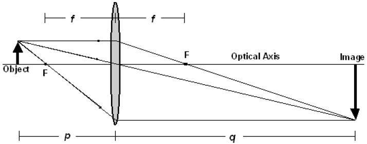
Figure 1
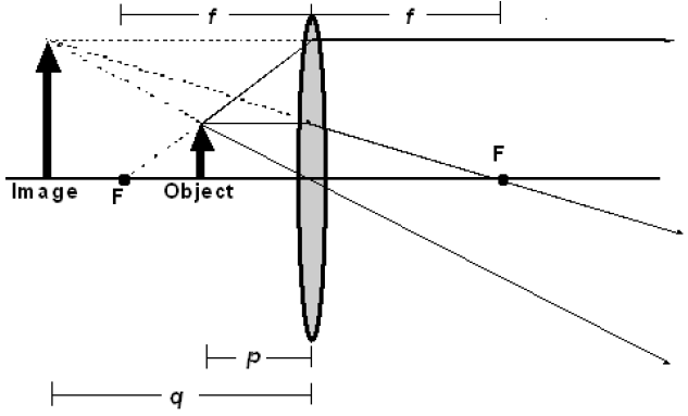
Figure 2
( 2 )
m ≡
=
| himage |
| hobject |
| h' |
| h |
( 3 )
m = −
| q |
| p |
-
•m > 0 (positive magnification) means the image is upright.
-
•m < 0 (negative magnification) means the image is inverted.
Procedure
Part 1: Measuring Focal Lengths Using a Ray Box
A lens is primarily characterized by its focal length, so it is worthwhile learning how to measure the focal length of a lens. Although the focal length does vary slightly for different frequencies or colors of light, in this lab we will be using visible white light sources, consistent with what manufacturers typically assume when they sell lenses marked with a unique focal length. Keep in mind that by convention, a convex (converging) lens has a positive focal length, and a concave (diverging) lens is indicated by a negative focal length.A. Convex (converging) lens
-
1Use a ray box and the black plastic card with various numbers of slits to form 3 or 5 parallel light rays. You will need to move the ray box housing relative to the light source to make the emerging rays parallel (not converging or diverging). It is important that these rays be parallel, otherwise the image distance will not be the focal length of the lens! What kind of measurement will you make to determine if the emerging rays are parallel?
-
2Place the plastic, double-convex lens on a sheet of paper and align the rays normal (perpendicular) to the lens so that the refracted rays converge on the opposite side at the focal point. Move the lens and ray box as needed to center the lens and focal point on the paper.
-
3Trace the incident and refracted rays on the paper, along with the outline of the lens. Be sure to draw arrows on the rays to indicate their direction (without arrows, the rays are simply lines).
-
4Use a ruler to measure the distance from the center of the lens to the point where the rays cross, and label this focal length f on the paper. Remember to include an estimate of the uncertainty in this measurement when reporting the focal length. Does your focal length measurement agree with that of other students? (All the lenses are made the same, so the measurements should agree.)
B. Concave (diverging) lens
Follow the same procedure as in Part A, this time using a concave lens. Since this lens diverges the light rays, you will have to find the focal point by extending the real rays backwards with dotted lines to show where the virtual image is located. This means you will need to shift the lens forward on the paper to allow sufficient space to locate the focal point on the front side of the lens. Once you measure the focal length, remember to use a negative sign to indicate that this is a diverging lens.
Note: Some light is reflected off the front surface of the concave lens, which in this case is acting
like a mirror. These rays form a real image, which is the focal point of the mirror, not the lens.
Part 2: Examining Images Using an Optics Bench
In this section, you will use a convex lens with a focal length f = 7.5 cm and examine how the image changes for several different object distances. An optics bench provides a convenient way to view the image and take measurements.A. Verify focal length of lens using a distant object
Before taking data with a lens, it is a good idea to measure, or at least verify, its focal length. The easiest way to do this for a convex lens is to find a bright distant object (like the sun or a light bulb), and the resulting image distance will be nearly the focal length. By using an object that is very far away, the incident rays are nearly parallel, like those produced by the ray box in Part 1. This relationship can also be seen from the thin lens equation (1)| 1 |
| p |
| 1 |
| q |
| 1 |
| f |
( 4 )
| 1 |
| ∞ |
| 1 |
| q |
| 1 |
| f |
| 1 |
| q |
| 1 |
| f |
1/p = 1/750
differs from the term 1/q = 1/7.5 by only 1%, and f = q with only a 1% error.
-
1Remove the light source from the optical bench. Place the viewing screen approximately 10 cm from the lens. Point the optical bench toward a distant light source and slowly move the viewing screen toward the lens until the image comes into focus. Record the image distance and the approximate object distance. Does the image distance equal the focal length marked on the lens?
-
2Replace the light source before beginning the next procedure.
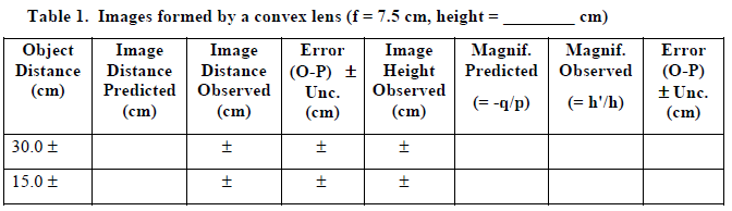
B. Examining images formed by a convex lens
-
1Use the thin lens equation to calculate the image distance and magnification you should expect and record the results in the following data table. Remember to include a copy of this table in your final report.
-
-
2Place the light source with the crossed arrow object at one end of the optics bench. Position the convex lens in front of the object for the first object distance in Table 1. Locate the image of the object with the viewing screen by slowly moving the screen away from the lens. The image will decrease in size and come into focus as the viewing screen approaches the image location. Beyond that point the image becomes fuzzy and its size increases. (Notice that due to aberrations in the lens, there is a range over which the image comes into focus. Consider this range when you are determining the uncertainty of your measurements.) When the image is at the point of optimum focus, measure as accurately as possible the distance from the center of the lens to the screen, and record this image distance in your data table.
-
3Measure as accurately as possible the height of the crossed arrow target, h.
-
4Measure as accurately as possible the height of the image, h'. (By convention, h' is negative if the image is upside-down, compared to the object.)
-
5Repeat the above process for the remaining object distances listed in Table 1.
-
6Predict what will happen to the image when you cover the top half of the object with a piece of paper. Test your prediction and explain your findings.
-
7Predict what will happen to the image when you cover the top half of the lens with a piece of paper. Test your prediction and explain your findings.
C. Examining images formed by a concave lens
-
1Place a concave lens (f = –15.0 cm) about 10 cm in front of the light source. Move the viewing screen away from the lens and describe what you see.
-
2Look through the concave lens back toward the light source. Is the virtual image magnified or minified? Is it upright or inverted?
Part 3: Lens System and Corrective Lenses
When two or more lenses are used together to make an image, the combination is called a lens system. A common lens system is found when eyeglasses or contact lenses are used in combination with the cornea of the eyeball to correct nearsightedness or farsightedness. The human eye acts much like the convex lens in Part 2B, except the eye uses a muscle to change the focal length of the lens to focus an image on the retina at the back of the eyeball. Since the image distance for the eyeball is fixed, there is a limited range that the cornea can change its focal length. Most eyeballs can comfortably focus on objects from infinity to a near point of about 25 cm, but some people have eyeballs that do not focus well near or far. People who are nearsighted can see objects that are close but have difficulty focusing on distant objects because their eyeball tends to form an image in front of the retina. Farsightedness occurs when distant objects can be seen but objects that are nearby are difficult to view clearly because the eyeball tends to form an image behind the retina. The following exercise will show how corrective lenses can change the focal point for these two common eyesight conditions.-
1Place a convex lens (f = 7.5 cm) 25 cm from the object. This lens represents the cornea of an eye. Use the lens equation to find the image location of this lens.
-
2Predict where the image should be formed when a second convex lens (f = 15.0 cm) representing corrective eyewear is placed 5 cm in front of the "cornea" (between the "cornea" and the object). To do this, let the image of the corrective lens be the object of the "cornea". (Note: This object distance should be negative since it is on the far side of the "cornea". Also remember to account for the distance between the two lenses. The image distance for this lens system should be measured from the center of the corrective lens.)
-
3Experimentally verify your prediction. Does your measurement of the image distance agree with your calculated prediction to within the uncertainty of your measurements?
-
4Repeat steps 2 and 3 for a concave lens (f = –15.0 cm).
-
5Which type of lens is needed to correct near-sightedness? Explain.
-
6Which type of lens is needed to correct far-sightedness? Explain.
Be sure that both you and your TA each initial your data, and that you hand in a copy of your
data before leaving the lab. Remember to pledge your work.