
Graphing Techniques
The construction of graphs is a very important technique in experimental physics. Graphs provide a compact and efficient way of displaying the functional relationship between two experimental parameters and of summarizing experimental results. Some graphs early in this lab course should be hand-drawn to make sure you understand all that goes into making an effective scientific graph. You will also learn how to use a computer to graph your data. When graphs are required in laboratory exercises in this manual, you will be instructed to "plot A vs. B" (where A and B are variables). By convention, A (the dependant variable) should be plotted along the vertical axis (ordinate) and B (the independent variable) should be along the horizontal axis (abscissa). Following is a typical example in which distance vs. time is plotted for a freely falling object. Examine this plot carefully, and note the following important rules for graphing: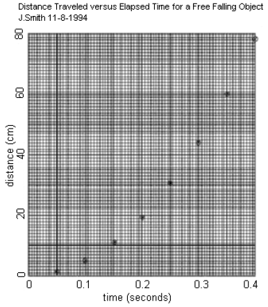
Figure 1
Graph Paper
Graphs that are intended to provide numerical information should always be drawn on squared or cross-section graph paper, 1 cm × 1 cm, with 10 subdivisions per cm. Use a sharp pencil (not a pen) to draw graphs, so that the inevitable mistakes may be corrected easily.Title
Every graph should have a title that clearly states which variables appear on the plot. Also, write your name and the date on the plot as well for convenient reference.Axis Labels
Each coordinate axis of a graph should be labeled with the word or symbol for the variable plotted along that axis and the units (in parentheses) in which the variable is plotted.Choice of Scale
Scales should be chosen in such a way that data are easy to plot and easy to read. On coordinate paper, every 5th and/or 10th line is slightly heavier than other lines; such a major division-line should always represent a decimal multiple of 1, 2, or 5 (e.g., 0, l, 2, 0.05, 20, 500, etc.). Other choices (e.g., 0.3) make plotting and reading data very difficult. Scales should be made no finer than the smallest increment on the measuring instrument from which data were obtained. For example, data from a meter stick (which has 1 mm graduations) should be plotted on a scale no finer than 1 division = 1 mm. A scale finer than 1 div/mm would provide no additional plotting accuracy, since the data from the meter stick are only accurate to about 0.5 mm. Frequently the scale must be considerably coarser than this limit, in order to fit the entire plot onto a single sheet of graph paper. In the illustration, scales have been chosen to give the graph a roughly square boundary; you should avoid choices of scale that make the axes very different in length. Note in this connection that it is not always necessary to include the origin ('zero') on a graph axis; in many cases, only the portion of the scale that covers the data need be plotted.Data Points
Enter data points on a graph by placing a small dot at the coordinates of the point and then drawing a small circle around the point. If more than one set of data is to be shown on a single graph, use other symbols (e.g. θ, Δ) to distinguish the data sets. A drafting template is useful for this purpose.Curves
Draw a simple smooth curve through the data points. The curve will not necessarily pass through all the points, but should pass as close as possible to each point, with about half the points on each side of the curve; this curve is intended to guide the eye along the data points and to indicate the trend of the data. A French curve is useful for drawing curved line segments. Do not connect the data points by straight-line segments in a dot-to-dot fashion. This curve now indicates the average trend of the data, and any predicted values should be read from this curve rather than reverting back to the original data points.Straight-line Graphs
In many of the exercises in this manual, you will be asked to graph your experimental results in such a way that there is a linear relationship between graphed quantities. In these situations, you will be asked to fit a straight line to the data points and to determine the slope and y-intercept from the graph. In the example given above, it is expected that the falling object's distance varies with time according tod =
gt2.
It is difficult to tell whether the data plotted in the first graph above agrees with this prediction. However, if d vs. t2 is plotted, a straight line should be obtained with slope = g/2 and y-intercept = 0.
| 1 |
| 2 |
Straight Line Fitting
Place a transparent ruler or drafting triangle on your graph and adjust its position so that the edge is as close as possible to all the data points. The best adjustment will bring about one-half of the data points beneath the ruler, evenly distributed along the line. Draw a line along the ruler edge that extends to the nearest coordinate axis at one end and somewhat beyond the last data point at the other end. The degree to which the data are consistent with the equation is shown by how close the data points are to the fitted line. The construction of this straight line performs a smoothing of the raw experimental data, and thus may be a more reliable indication of the outcome of the experiment than any one pair of data points. Measurements taken from the graph should therefore be made on the fitted line and not on the data points themselves. Do not 'force' the fitted line to pass through the origin of your graph, even though the presumed mathematical function passes through (0, 0), as in the example functiond = (g/2)t2.
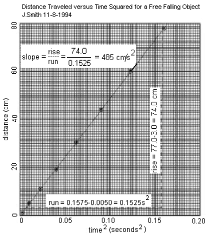
Figure 2
Obtaining the Slope and Intercept
The slope of a straight line is computed by dividing the 'rise' by the 'run' of the line, as shown. For the 'run', choose two convenient scale locations along the horizontal axis near the ends of the line, and draw light vertical lines to intersect the plotted line. Read off the positions of these intersections along the vertical axis and subtract to obtain the 'rise'. Always report the calculated slope on the graph itself. You may find it helpful to label 'rise' and 'run' and intersection points as shown in the example, at least until your graphing technique is well developed. When you are asked to determine the intercept with the y-axis, label the intercept where the plotted line intersects the vertical axis (assuming that the vertical axis is located at the '0' position along the horizontal scale).Uncertainty in the Slope and Intercept
The uncertainty in the slope and intercept can be estimated by drawing two more straight lines with the maximum and minimum slope that still allows the lines to pass through most of the data points. The corresponding range of slopes and intercept values can then be used as a reasonable estimate of the uncertainty in these values.Least Squares Fitting
Consider two physical variables, x and y, that we expect to be connected by a linear relationship:y = a + bx.
A graph of y vs. x should be a straight line which has a slope of b and intersects the y-axis at the intercept y = a.
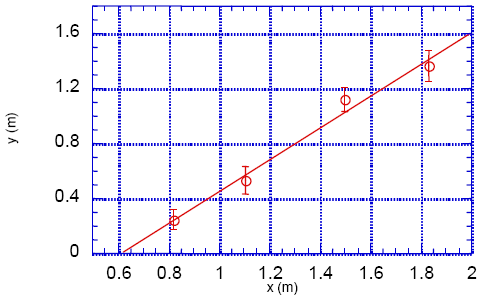
Figure 3
(x1, y1), (x2, y2),  , (xN, yN).
Assume that the measurements of x have negligible error and the measurements of y have standard errors , (xN, yN). σ1, σ2, , σN.
The graph of such a set of measurements is illustrated in Figure 3. We want to find the straight-line , σN. y = a + bx,
which amounts to finding the best estimates for a and b. In the linear least square fitting procedure, the best estimates for a and b are those that minimize the weighted sum of squares (Chi-squared):
( 1 )
χ2 =
| N |
| ||||||
 | |||||||
| i = 1 |


a + bxi
is the expected value of y when x = xi,
thus yi − (a + bxi)
is just the deviation of the measured value of y from the expected value. The least squares method therefore finds values of a and b that minimize the sum of the squares of these deviations weighted by their respective uncertainty.
In this lab, you will use data analysis software like Excel which can automatically calculate the best values of a and b and their respective error, σa
and σb.
If your data points have widely varying errors, then those with large errors should be given less weight. Therefore, the weighted fit version should be used for these cases. If all data points are to be given equal weight, then the unweighted fit should be used.