
Chapter 6 – Molecular Structure
Introduction
A method for constructing Lewis structures of simple molecules and ions was presented in Chapter 5. In this chapter, we show how to use Lewis structures to determine the structural and bonding properties of molecules and ions with covalent bonds.6.1 Molecular Shapes
Introduction
A molecule is a three-dimensional structure, and many of its properties, both chemical and physical, are dictated by that structure. The Lewis structure of a molecule is a two-dimensional representation that can be used to obtain information about its three-dimensional structure. Determining the shape of a molecule from its Lewis structure is the topic of this lesson.Prerequisites
-
•1.8 Electromagnetism and Coulomb's Law
-
•2.6 Orbital Shapes and Sizes
-
•5.6 Determining Lewis Structures (Draw Lewis structures.)
Objectives
-
•Determine the number of electron regions around an atom.
-
•Rate the relative strengths of lp-lp, lp-bp, and bp-bp interactions.
-
•Name the molecular shapes of simple molecules that contain a single central atom.
-
•Use lines, wedges, and dashes to represent the 3D structure of an atom with four electron regions.
-
•Distinguish between a ball-and-stick model and a space-filling model.
6.1-1. Electron Regions
One electron group or region can be either a lone pair, a single bond, a double bond, or a triple bond.
-
•lone pair
-
•single bond
-
•double bond
-
•triple bond
6.1-2. Counting Electron Regions Exercise
Exercise 6.1:

What is the number of electron regions around the sulfur atom in each of the following?

3_0__
There are four bonds around the sulfur, but only 3 electron regions because the double bond produces a single electron region.


6.1-3. VSEPR Video
- Viewing the Video
-
•View the video in this window by selecting the play button.
-
•Use the video controls to view the video in full screen.
-
•View the video in text format by scrolling down.
6.1-4. VSEPR Summary
In summary, the three possible orientations of electron groups around an atom that obeys the octet rule are the following.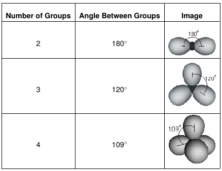
Table 6.1
6.1-5. Bond Angles
If all of the electron groups around a central atom are not identical, the predicted bond angles are only approximate.
lone pair-lone pair > lone pair-bonding pair > bonding pair-bonding pair
-
1Determine the number of electron groups around the atom where the angle forms.
-
2If there are no lone pairs and the atoms are nearly the same size, the angle will be 180°, 120°, or 109°.
-
3If there are lone pairs, the angles decrease from the values predicted in step 2. The deviation is greater for two lone pairs than for one.
6.1-6. Ordering Bond Angles Exercise
Exercise 6.2:
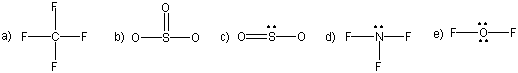
Consider the Lewis structures of CF4, SO3, SO2, NF3, and OF2, which are given below. Note, only lone pairs around the central atom are shown.
Indicate the molecule with the greater bond angles in each pair.
-
SO3 or CF4
-
SO3
-
CF4 The bond angles are the greatest around the atom with the smaller number of electron groups. There are three groups around the S in SO3, while there are four groups around the C in CF4. Consequently, the bond angles are greater in SO3 (120°) than in CF4 (109°).
-
SO3 or SO2
-
SO3
-
SO2 There are three electron groups around each sulfur atom, so both molecules have O–S–O bond angles near 120°. However, one of the electron regions in SO2 is a lone pair, which repels the bonding pairs more than another bonding pair. Consequently, the bond angles in SO3, which are 120° are predicted to be greater than those in SO2, which are close to, but less than, 120°.
-
NF3 or OF2
-
NF3
-
OF2 There are four electron groups around each central atom, so both molecules have bond angles near 109°. However, one of the electron regions in NF3 is a lone pair, while two electron regions in OF2 are lone pairs. The lone pair affects the bond angles more than bonding pairs. Consequently, the bond angles in NF3 are predicted to be greater than those in OF2, although both are ~109°.
6.1-7. Molecular Shapes
The locations occupied by the lone pairs are not used when describing the shape of a molecule.
-
1Determine the number of electron groups around the central atom.
-
2Determine which of the shapes shown in Table 6.1 applies.
-
3Name the molecular shape adopted by the atoms.
6.1-8. The Common Shapes
Three atoms can be either linear or bent and four atoms can be planar or pyramidal; which geometry is adopted depends upon the presence of lone pairs.
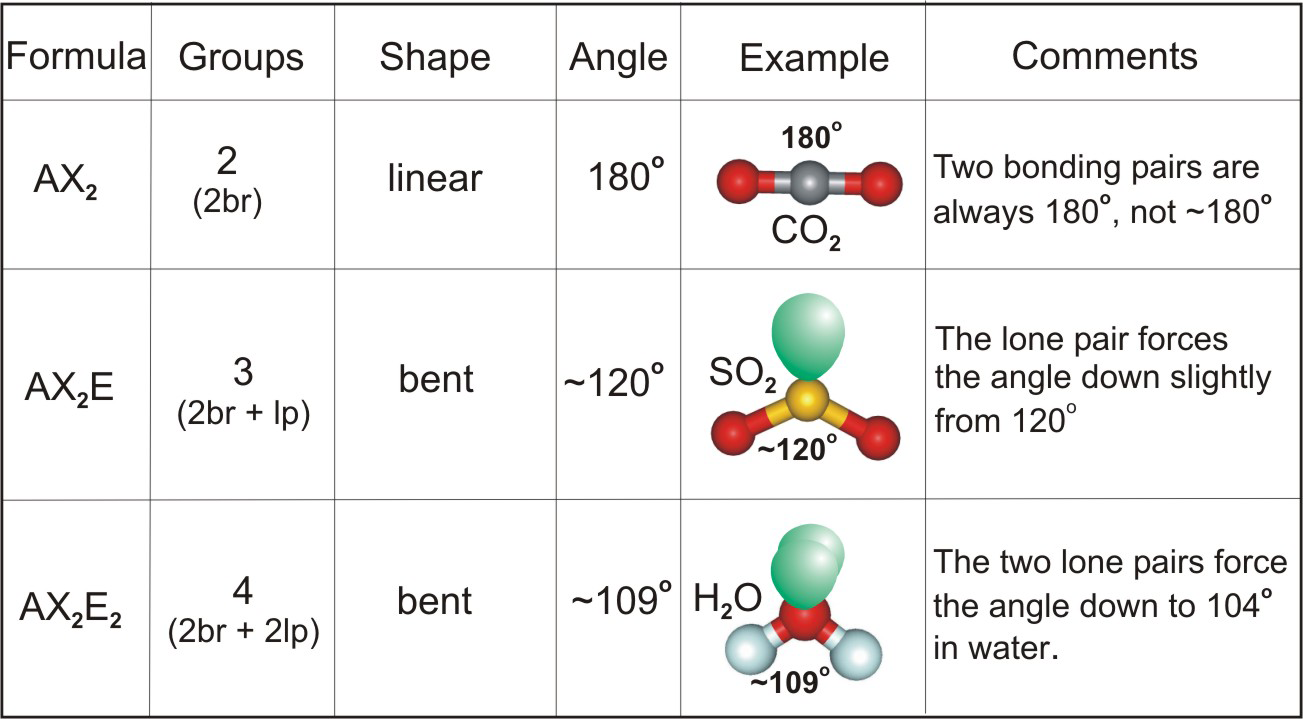
Table 6.2

Table 6.3
6.1-9. Molecular Representations
Ball-and-stick representations are better for showing bond angles, but space-filling representations are closer to how we envision molecules.

Figure 6.4: Line-Wedge-Dash Representation of a Tetrahedral Geometry
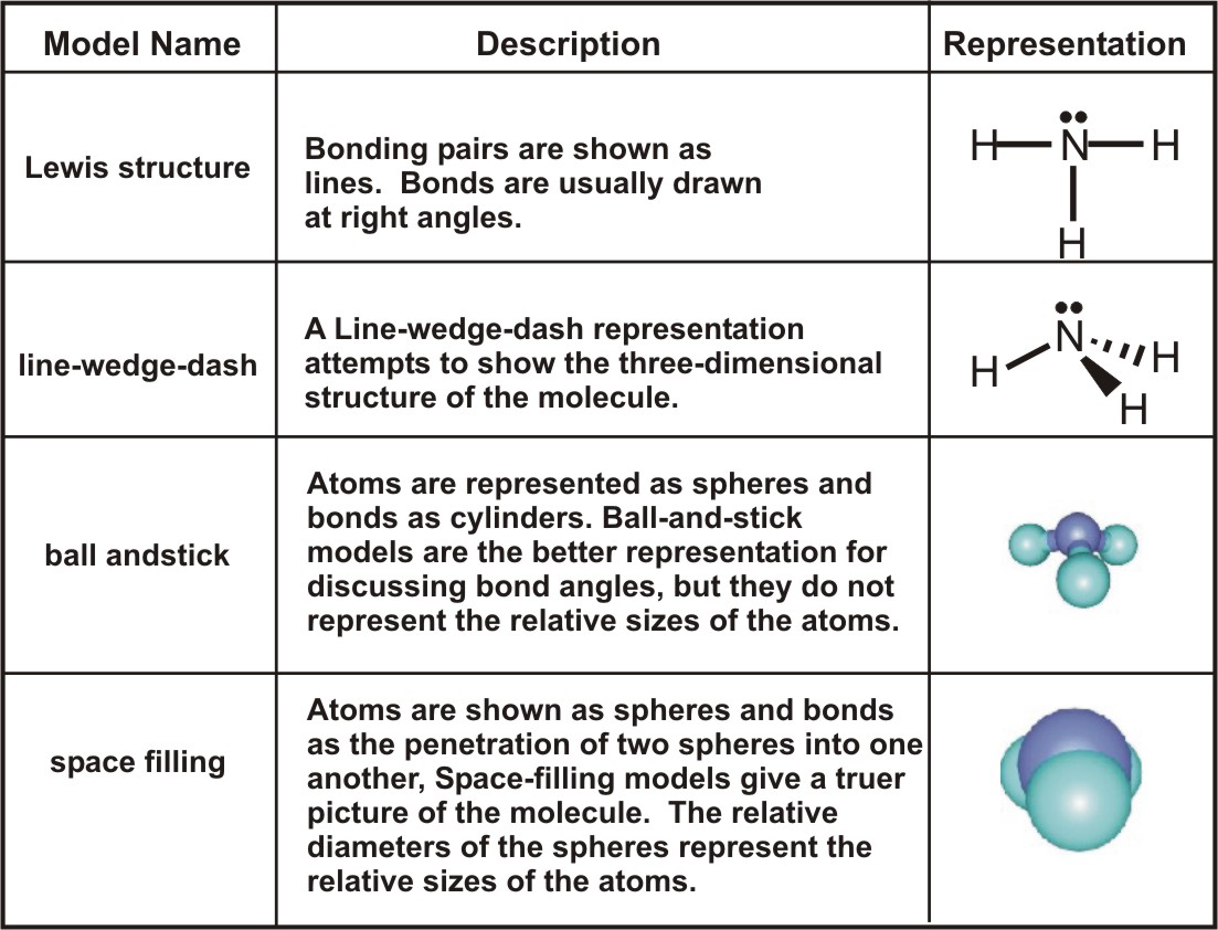
Table 6.5
6.1-10. Structure Exercise
Exercise 6.3:
Draw the Lewis structure to describe the shape and give the approximate bond angles of the following ions.
-
ClO21– shape
-
linear ER=24; VE=20; SP=2. There are two bonding pairs, so there must also be two lone pairs on the central atom to give it an octet. The four electron regions make the ion bent.
-
bent
-
planar ER=24; VE=20; SP=2. There are two bonding pairs, so there must also be two lone pairs on the central atom to give it an octet. The four electron regions make the ion bent.
-
pyramidal ER=24; VE=20; SP=2. There are two bonding pairs, so there must also be two lone pairs on the central atom to give it an octet. The four electron regions make the ion bent.
-
tetrahedral ER=24; VE=20; SP=2. There are two bonding pairs, so there must also be two lone pairs on the central atom to give it an octet. The four electron regions make the ion bent.
-
ClO21– approximate bond angle
-
90° Bent ions with two lone pairs on the central atom have 109° bond angles.
-
109°
-
120° Bent ions with two lone pairs on the central atom have 109° bond angles.
-
180° Bent ions with two lone pairs on the central atom have 109° bond angles.
-
N31– shape
-
linear
-
bent ER=24; VE=16; SP=4. There are four bonding pairs, so there can be no lone pairs on the central atom. The ion is linear.
-
planar ER=24; VE=16; SP=4. There are four bonding pairs, so there can be no lone pairs on the central atom. The ion is linear.
-
pyramidal ER=24; VE=16; SP=4. There are four bonding pairs, so there can be no lone pairs on the central atom. The ion is linear.
-
tetrahedral ER=24; VE=16; SP=4. There are four bonding pairs, so there can be no lone pairs on the central atom. The ion is linear.
-
N31– approximate bond angle
-
90° The ion is linear, so the bond angle is 180°.
-
109° The ion is linear, so the bond angle is 180°.
-
120° The ion is linear, so the bond angle is 180°.
-
180°
-
PO33– shape
-
linear ER=32; VE=26; SP=3. There are three bonding pairs, so there must be one lone pair on the central atom, and the ion must be pyramidal.
-
bent ER=32; VE=26; SP=3. There are three bonding pairs, so there must be one lone pair on the central atom, and the ion must be pyramidal.
-
planar ER=32; VE=26; SP=3. There are three bonding pairs, so there must be one lone pair on the central atom, and the ion must be pyramidal.
-
pyramidal
-
tetrahedral ER=32; VE=26; SP=3. There are three bonding pairs, so there must be one lone pair on the central atom, and the ion must be pyramidal.
-
PO33– approximate bond angle
-
90° The bond angles in pyramidal ions with a lone pair on the central atom are ~109°.
-
109°
-
120° The bond angles in pyramidal ions with a lone pair on the central atom are ~109°.
-
180° The bond angles in pyramidal ions with a lone pair on the central atom are ~109°.
-
NO31– shape
-
linear ER=32; VE=24; SP=4. There are four bonding pairs, so there are no lone pairs on the central atom and the ion must be planar.
-
bent ER=32; VE=24; SP=4. There are four bonding pairs, so there are no lone pairs on the central atom and the ion must be planar.
-
planar
-
pyramidal ER=32; VE=24; SP=4. There are four bonding pairs, so there are no lone pairs on the central atom and the ion must be planar.
-
tetrahedral ER=32; VE=24; SP=4. There are four bonding pairs, so there are no lone pairs on the central atom and the ion must be planar.
-
NO31– approximate bond angle
-
90° The bond angles in trigonal planar ion with identical groups are 120°.
-
109° The bond angles in trigonal planar ion with identical groups are 120°.
-
120°
-
180° The bond angles in trigonal planar ion with identical groups are 120°.
-
BrO41– shape
-
linear Four groups around a central atom that obeys the octet rule are arranged in a tetrahedron.
-
bent Four groups around a central atom that obeys the octet rule are arranged in a tetrahedron.
-
planar Four groups around a central atom that obeys the octet rule are arranged in a tetrahedron.
-
pyramidal Four groups around a central atom that obeys the octet rule are arranged in a tetrahedron.
-
tetrahedral
-
BrO41– approximate bond angle
-
90° The bond angles in a tetrahedron with identical groups are 109°.
-
109°
-
120° The bond angles in a tetrahedron with identical groups are 109°.
-
180° The bond angles in a tetrahedron with identical groups are 109°.
6.2 Central Atoms With More Than Four Electron Regions
Introduction
The octet rule applies rigidly only to C, N, O and F, and even nitrogen violates it occasionally because it has an odd number of electrons in some of its molecules. Atoms with more than eight valence electrons are said to have expanded valence shells or expanded octets. Transition metals and the heavier p block elements frequently use expanded octets. In this section, we discuss the shapes of molecules in which the central atom has five and six electron regions.Objectives
-
•Name the shapes adopted around atoms with five and six electron regions.
6.2-1. Shapes of Five and Six Electron Regions

Figure 6.6a: Five Electron Regions

Figure 6.6b: Six Electron Regions
6.2-2. Determining Structures of Expanded Octets with Lone Pairs
The number of lone pairs around a central atom (LP) can be determined from its group number and its oxidation state as follows. Atoms with expanded valence shells can be identified because the predicted number of shared pairs is always too small to accommodate all of the bonds. See the following example.Example:
We determine for SF4: ER = 5(8) = 40 electrons; VE = 6 + 4(7) = 34 electrons; SP = 1/2(40 – 34) = 3 shared pairs. However, a minimum of 4 shared pairs is required for the four S-F bonds, so the three shared pairs cannot be correct and the octet rule cannot be obeyed. The group number of sulfur is 6 and its oxidation state in SF4 is +4, so the number of lone pairs around the sulfur atom is LP = 1/2(6 – 4) = 1 lone pair. Thus, there are five electron groups around the sulfur: four S-F bonds and one lone pair. As shown below, the five groups adopt the trigonal bipyramidal structure with the lone pair in the equatorial plane.

We determine for SF4: ER = 5(8) = 40 electrons; VE = 6 + 4(7) = 34 electrons; SP = 1/2(40 – 34) = 3 shared pairs. However, a minimum of 4 shared pairs is required for the four S-F bonds, so the three shared pairs cannot be correct and the octet rule cannot be obeyed. The group number of sulfur is 6 and its oxidation state in SF4 is +4, so the number of lone pairs around the sulfur atom is LP = 1/2(6 – 4) = 1 lone pair. Thus, there are five electron groups around the sulfur: four S-F bonds and one lone pair. As shown below, the five groups adopt the trigonal bipyramidal structure with the lone pair in the equatorial plane.
6.2-3. Expanded Octet Structure Exercise
Exercise 6.4:
Determine the number of lone pairs on the central atom in and the structures of XeF2 and BrF41–.
XeF2
group number
8_0__
Xe is a noble gas.
oxidation state
2___0
F is always –1 and there are two of them.
lone pairs
3_0__
1/2(8 – 2) = 3
number of electron regions
5_0__
Three lone pairs plus 2 bonding pairs.
-
Are the three atoms linear or bent?
-
linear The lone pairs adopt the equatorial positions.

-
bent
BrF41–
group number
7_0__
Br is a halogen.
oxidation state
3_0__
The sum of the oxidation states must equal the charge on the ion.
lone pairs
2_0__
1/2(7 – 3) = 2
number of electron regions
6_0__
Two lone pairs plus 4 bonding pairs.
-
Do the five atoms lie in a plane?
-
Yes
-
No The lone pairs are opposite one another.

6.3 Larger Molecules
Introduction
Groups connected by single bonds can rotate relative to one another about the bond, so VSEPR cannot be used to predict the exact structure of complicated molecules, but it can be used to look at the geometry around individual atoms. In this section, we examine the structure of three common molecules: acetic acid (the active ingredient in vinegar), benzene, and aspirin.Objective
-
•Predict bond angles in larger molecules.
6.3-1. Acetic acid
We deduce the following bond angles in acetic acid from its Lewis structure.-
1α ~109° because there are four electron regions around the carbon 1.
-
2β ~120° because the C at 2 is surrounded by three electron regions.
-
3γ ~109° because there are four electron regions around the oxygen atom at 3.

Figure 6.7: Acetic Acid
6.3-2. Benzene
Benzene has the formula C6H6 and is a six-membered ring (the six carbon atoms bond so as to form a hexagon). The Lewis structures of its two resonance forms that are shown in Figure 6.8a. We conclude the following based on these Lewis structures.-
1Each carbon has three regions, so each is trigonal planar and all bond angles are 120°.
-
2The double bonds require that the molecule is planar.
-
3As a result of resonance, all of the carbon atoms are identical as are all six of the bonds between them. The measured C-C bond lengths are all 1.4 Å. Thus, the bond lengths all lie between the 1.5 Å of a single C-C bond and the 1.3 Å of a C=C double bond, which is consistent with a bond order of 1.5. The three double bonds are threfore shared equally between the six bonding regions in the ring. Indeed, the double bonds are frequently represented as a circle rather than three lines (Figure 6.8b) to emphasize the equivalence of the carbon-carbon bonds. We will revisit this important bonding characteristic of benzene in our discussion of molecular orbital theory at the end of the chapter.

Figure 6.8: Benzene
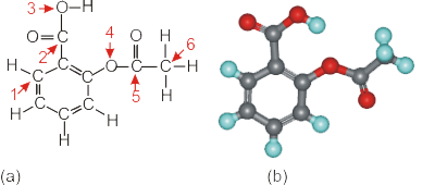
6.3-3. Aspirin
-
1Carbon atoms at positions 1, 2, and 5 all have three regions, so their bond angles are ~120°.
-
2The carbon at position 6 has four regions, so the bond angles there are ~109°.
-
3Oxygen obeys the octet rule, but only four electrons (two bonding pairs) are shown in the Lewis structure. Consequently, two lone pairs must be added to each to produce four regions, which requires bond angles of ~109°.
-
4Aspirin contains the same structural features that are found in acetic acid and benzene.

Figure 6.9: Aspirin
6.3-4. Predicting Bond Angles Exercise
Exercise 6.5:
The structure below is that of capsaicin, the molecule responsible for the heat in chili peppers. Estimate each of the labeled bond angles. Note that lone pairs are not drawn, but C and O both obey the octet rule. Enter only the number, not the degree sign (°).
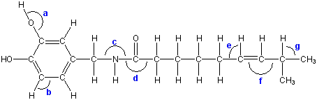
a
109_0__
There are also two lone pairs on the O, so there are four electron regions.
°
b
120_0__
There are three electron regions.
°
c
109_0__
There is also one lone pair on the N, so there are four electron regions.
°
d
120_0__
There are three electron regions.
°
e
120_0__
There are three electron regions.
°
f
120_0__
There are three electron regions.
°
g
109_0__
There are four electron regions.
°
6.4 Valence Bond Theory and Hybridization
Introduction
In valence bond theory, each bond results from the overlap of two atomic orbitals on adjacent atoms. The bonding electrons in such bonds are localized in the region between the two atoms. A single bond is composed of two bonding electrons, so the total number of electrons in the two overlapping atomic orbitals used to produce a bond cannot exceed two. In most cases, each orbital contains one electron, and the two electrons pair when the orbitals overlap. However, both electrons can reside in one of the atomic orbitals (a lone pair), but, in this case, the other orbital must be empty. A bond in which a lone pair is converted into a covalent bond is called a coordinate covalent bond. Coordinate covalent bonds are produced in Lewis acid-base reactions, which are discussed in Chapter 12. We limit our discussion here to cases where each overlapping orbital has one electron.Objective
-
•Define the term hybridization and name the types of hybrid orbitals used by atoms that obey the octet rule.
6.4-1. Sigma Bonds
The bonding in diatomic molecules can be explained with the overlap of the atomic orbitals that contain unpaired electrons. Bonds formed from the end-on overlap of orbitals place electron density on the internuclear axis (shown as the dotted line in the figures) and are called sigma (σ) bonds. As examples of σ bond formation, we consider the cases of H2, F2, and HF. Note that the electrons are shown as arrows and the overlap region is shown in yellow in the figures.
Figure 6.10a: Bond from Overlap of Atomic Orbitals

Figure 6.10b: Bond from Overlap of Atomic Orbitals

Figure 6.10c: Bond from Overlap of Atomic Orbitals
6.4-2. Pi Bonds
Pi Bond
- Viewing the Video
-
•View the video in this window by selecting the play button.
-
•Use the video controls to view the video in full screen.
-
•View the video in text format by scrolling down.

Figure 6.11: Pi Bond
6.4-3. Valence Bond Description of O2 Bonding
O2 is a diatomic molecule that contains both σ and π bonds. The valence electron configuration of an oxygen atom is 2s2 2p4, so there are paired electrons in the 2s and one of the 2p orbitals. The unpaired electrons in an oxygen atom lie in the other two p orbitals. In Figure 6.12, the unpaired electrons are assumed to be in the pz and py orbitals. As the atoms approach along the z-axis, the pz orbitals of the two oxygen atoms overlap in an end-on fashion (orange line) to produce an σ bond, while the py orbitals overlap side-on (both violet lines) to produce a π bond. Thus, the O=O double bond consists of one σ and one π bond. All bonds contain one and only one σ bond. Double bonds contain one σ and one π bond, and triple bonds contain one σ and two π bonds. The bond order of a bond is simply the sum of the number of σ and π bonds that it contains.
Figure 6.12: Valence Bond Picture of O2 Bonding
6.4-4. Hybrid Orbitals
The simple overlap of atomic orbitals used for diatomic molecules cannot be used for larger ones. Consider the molecule formed between a carbon atom and hydrogen atoms. Carbon has a valence electron configuration of 2s22p2, so it has two unpaired electrons in its p orbitals. If carbon used only atomic orbitals with one electron, its compound with hydrogen would be CH2, and the H-C-H bond angle would be 90° (the angle between two p orbitals). However, the simplest compound involving carbon and hydrogen is CH4, which has the 109° bond angles predicted from VSEPR. In order to account for molecular geometries in the valence bond model, orbitals on a central atom must be combined to produce new orbitals before they overlap with the orbitals of another atom. By choosing the appropriate combination of the atomic orbitals, we can create orbitals that have the geometries required by VSEPR. Orbitals produced by combining two or more atomic orbitals on the same atom are called hybrid orbitals, and the process by which they are formed is called hybridization. However, before we can understand hybridization, we must examine how orbitals combine.6.4-5. Orbital Phase
To understand the process of combining orbitals, we must first review the nature of atomic orbitals. Recall from Chapter 2 that atomic orbitals describe algebraic functions that are solutions to an atom's wave equation, and that the phase or algebraic sign of an orbital in a particular region is frequently indicated with shading (Section 2.6). In Figure 6.13, we adopt the convention of using blue to indicate regions where the function is positive and red for regions where it is negative.
Table 6.13
6.4-6. An Example of Mixing Two Functions
Mixing orbitals is the mathematical combination of these functions by addition and/or subtraction. Consider the two combinations of the functions P and Q shown in the Figure 6.14. Regions where the functions are positive are shaded in blue, while negative regions are shown in red. This is consistent with our use of these colors to describe the sign of orbital functions. In Figure 6.14a, the two functions are added to produce functionR = P + Q.
R is amplified on the ends because both P and Q have the same phase (sign) there, but it is reduced dramatically in the center because the phases of P and Q are opposite there. We conclude the following.
Adding regions of the same phase (blue + blue) is constructive and produces a region of increased amplitude, while adding regions of opposite phase (blue + red) is destructive and produces a region of decreased or even annihilated amplitude.
S = P − Q
in the Figure 6.15b, the phase of Q is reversed (its sign is changed) to produce –Q and then the two waves are added to produce S. The ends of P and –Q have different phases, so they add destructively to nearly annihilate one another, while the regions in the middle have the same phase and add constructively to produce an amplified region in S.

Figure 6.14: Mixing Two Functions
6.4-7. Rules for Mixing
Use the following rules when mixing orbitals.-
1The number of orbitals produced must always equal the number of atomic orbitals used to construct them.
-
2Regions in which the atomic orbitals have the same sign (shading) add constructively, which makes the produced orbital larger in that region, but regions where the orbitals have opposite phases add destructively, which makes the combined orbital smaller in that region.
6.4-8. Hybridizing an s and a p Orbital
Mixing an s and a p Orbital on the Same Atom
- Viewing the Video
-
•View the video in this window by selecting the play button.
-
•Use the video controls to view the video in full screen.
-
•View the video in text format by scrolling down.

Figure 6.15: Mixing an s and a p Orbital on the Same Atom
6.4-9. Hybrid Orbital Descriptions
The number of hybrid orbitals used by an atom equals the number of electron groups around the atom.

Figure 6.16a: A Hybridization Used by Atoms Obeying the Octet Rule

Figure 6.16b: A Hybridization Used by Atoms Obeying the Octet Rule

Figure 6.16c: A Hybridization Used by Atoms Obeying the Octet Rule
6.4-10. Using Valence Bond Theory to Explain the Structure of Allene
We conclude our discussion of valence bond theory by using it to explain why the planes of the two CH2 groups of allene are perpendicular.- Viewing the Video
-
•View the video in this window by selecting the play button.
-
•Use the video controls to view the video in full screen.
-
•View the video in text format by scrolling down.
-
•Jump to the exercises for this topic.

Figure 6.17: Coordinate System Used in Allene
Bonding and Hybridization Examples
6.4-11. Aspirin
Exercise 6.6:
Indicate the hybridization as sp, sp2, or sp3 at each of the labeled atoms in the Lewis structure of the aspirin molecule shown below. Note that the lone pairs have been omitted, but C and O do obey the octet rule.
-
C1
-
sp C1 has three electron regions, so it is sp2 hybridized. The three sp2 hybrid orbitals are used in two C–C σ bonds and one C–H σ bond. The p orbital that is not used in the construction of the hybrid orbitals is involved in a π bond. Note C1 is in a benzene ring.
-
sp2
-
sp3 C1 has three electron regions, so it is sp2 hybridized. The three sp2 hybrid orbitals are used in two C–C σ bonds and one C–H σ bond. The p orbital that is not used in the construction of the hybrid orbitals is involved in a π bond. Note C1 is in a benzene ring.
-
C2
-
sp C2 has three electron regions around it, so it is sp2 hybridized. The three sp2 orbitals are used in a C–C σ bond and two C–O σ bonds. The remaining p orbital is used in the CO π bond. Note that C2 is in the acid group described for acetic acid.
-
sp2
-
sp3 C2 has three electron regions around it, so it is sp2 hybridized. The three sp2 orbitals are used in a C–C σ bond and two C–O σ bonds. The remaining p orbital is used in the CO π bond. Note that C2 is in the acid group described for acetic acid.
-
O3
-
sp O3 has four electron regions, so it is sp3 hybridized. The four hybrids are used in two σ bonds (O–H and C–O) and two lone pairs that are not shown. Oxygen always obeys the octet rule, so lone pairs must frequently be added to give oxygen an octet.
-
sp2 O3 has four electron regions, so it is sp3 hybridized. The four hybrids are used in two σ bonds (O–H and C–O) and two lone pairs that are not shown. Oxygen always obeys the octet rule, so lone pairs must frequently be added to give oxygen an octet.
-
sp3
-
O4
-
sp O4 has four electron regions (2 σ bonds + 2 lone pairs), so it is sp3 hybridized. Note that the two lone pairs that are not shown but are required to obtain an octet for oxygen.
-
sp2 O4 has four electron regions (2 σ bonds + 2 lone pairs), so it is sp3 hybridized. Note that the two lone pairs that are not shown but are required to obtain an octet for oxygen.
-
sp3
-
C5
-
sp C5 contains three electron groups, so it is sp2 hybridized. The three groups are all used in σ bonds (2C–C + 1C–O). The p orbital that is not used in the hybridization is used in the C=O pi bond.
-
sp2
-
sp3 C5 contains three electron groups, so it is sp2 hybridized. The three groups are all used in σ bonds (2C–C + 1C–O). The p orbital that is not used in the hybridization is used in the C=O pi bond.
-
C6
-
sp C6 contains four σ bonds (3C–H and 1C–C), so it is sp3 hybridized.
-
sp2 C6 contains four σ bonds (3C–H and 1C–C), so it is sp3 hybridized.
-
sp3
6.4-12. C2F4
Exercise 6.7:
Lewis structure and bonding in tetrafluoroethylene (C2F4):
 The double bond must go between the carbon atoms because double bonds are never drawn to fluorine as that places positive formal charge on the fluorine atom. Note that each fluorine atom has three lone pairs, which are not shown.Determine the following for C2F4.
-
•ER = 6(8) = 48 electrons required with no sharing
-
•VE = 2(4) from C + 4(7) from F = 36 valence electrons
-
•SP = 1/2(48 - 36) = 6 shared pairs
C-C bond order
2_0__
The C-C bond is a double bond, i.e., BO = 2.
-
the hybridization of each carbon atom:
-
sp There are three electron regions around each carbon, so each is sp2 hybridized.
-
sp2
-
sp3 There are three electron regions around each carbon, so each is sp2 hybridized.
the number of σ bonds
5_0__
There are five σ bonds (1 C-C + 4 C-F) bonds.
the number of π bonds
1_0__
There is one π bond in the C=C double bond.
6.4-13. C3H6
Exercise 6.8:
Lewis structure and bonding in propene (C3H6):
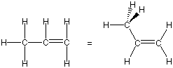 The six C-H bonds must all be single bonds, two more bonds are required to connect the three carbon atoms for a total of eight shared pairs. The Lewis structure requires nine shared pairs, so one C-C double bond is required.
Determine the following for C3H6.
-
•ER = 3(8) + 6(2) = 36 electrons required with no sharing
-
•VE = 3(4) from C + 6(1) from H = 18 valence electrons
-
•SP = 1/2(36 - 18) = 9 shared pairs
Determine the following for C3H6.
left C-C bond order
1_0__
The C-C bond is a single bond, i.e., BO = 1.
right C-C bond order
2_0__
The C-C bond is a double bond, i.e., BO = 2.
-
the hybridization of the leftmost carbon atom
-
sp There are four electron regions around the carbon, so it is sp3 hybridized.
-
sp2 There are four electron regions around the carbon, so it is sp3 hybridized.
-
sp3
-
the hybridization of the rightmost carbon atom
-
sp There are three electron regions around the carbon, so it is sp2 hybridized.
-
sp2
-
sp3 There are three electron regions around the carbon, so it is sp2 hybridized.
the number of σ bonds
8_0__
There are eight σ bonds (2 C-C + 6 C-H).
the number of π bonds
1_0__
There is one π bond in the C=C double bond.
6.4-14. C2O42–
Exercise 6.9:
Lewis structure and bonding in the oxalate ion (C2O42–):
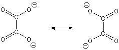 Five shared pairs are required for the sigma bonds, but seven shared pairs are required, so there must be two double bonds. This can only be accomplished while obeying the octet rule with one C=O double bond to each carbon.
Determine the following for C2O42–.
-
•ER = 6(8) = 48 electrons required with no sharing
-
•VE = 2(4) from C + 4(6) from O + 2 from charge = 34 valence electrons
-
•SP = 1/2(48 - 34) = 7 shared pairs
Determine the following for C2O42–.
C-C bond order
1_0__
The C-C bond is a single bond, i.e., BO = 1.
C-O bond order
1.5_0__
The C-O bonds are equivalent due to resonance, so the six shared pairs are shared equally among the four C-O regions. Thus, BO = 1.5.
-
the hybridization of each carbon atom
-
sp There are three electron regions around each carbon, so each is sp2 hybridized.
-
sp2
-
sp3 There are three electron regions around each carbon, so each is sp2 hybridized.
the number of σ bonds
5_0__
There are five σ bonds (1 C-C + 4 C-0).
the number of π bonds
2_0__
There are two π bonds in the C-O bonds.
6.4-15. CO32–
Exercise 6.10:
Lewis structure and bonding in the carbonate ion (CO32–):
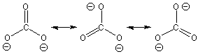 The lone pairs on the O atoms have been omitted, but each O obeys the octet rule.
Determine the following for CO32–.
-
•ER = 4(8) = 32 electrons required with no sharing
-
•VE = 4 from C + 3(6) from O + 2 from charge = 24 valence electrons
-
•SP = 1/2(32 - 24) = 4 shared pairs
Determine the following for CO32–.
C-O bond order
1.3333333_0.0333333__
The three C-O bonds are equivalent due to resonance, so the four shared pairs are shared equally in the three C-O regions. Thus, BO = 4/3 = 1.3.
-
the hybridization of the carbon atom
-
sp There are three electron regions around the carbon, so its is sp2 hybridized.
-
sp2
-
sp3 There are three electron regions around the carbon, so its is sp2 hybridized.
the number of σ bonds
3_0__
There are three σ bonds (3 C-0).
the number of π bonds
1_0__
There is one π bond shared among all of the C-O regions.
6.4-16. Bonding from Structure
Exercise 6.11:
X-rays are scattered from the atoms in molecules, and the manner in which they are scattered can be used to determine the relative positions of the atoms. Indeed, the structures of many molecules have been determined with this technique. However, x-rays are not scattered by electrons, and H atoms are usually too small to be seen. Consequently, lone pairs and H atoms must be added by the chemist.Determine the number of hydrogen atoms that must be added to the central carbon atom and the hybridization of the central atom of the structures given in the activity area. Hint:
-
•use bond lengths (see table in the Resources) to determine bond orders and bond angles to determine hybridizations, and
-
•recall that C usually has no formal charge, which is the case when there are 4 bonds to it.

-
What is the hybridization on the central carbon atom?
-
sp A 120° bond angle indicates sp2 hybridization, which means that the central carbon atom is involved in three sigma and one pi bond.
-
sp2
-
sp3 A 120° bond angle indicates sp2 hybridization, which means that the central carbon atom is involved in three sigma and one pi bond.
How many hydrogen atoms must be added to the central carbon atom?
0_0__
- A C-O bond length of 1.3 A is between the normal single (1.4 A) and double (1.2 A) bond lengths. So the two C-O bonds have bond orders of 1.5, i.e., there are two resonance structures.
- A C-C bond length of 1.5 A indicates a single bond.
- The central carbon atom has four bonds (3 σ + 1 π) and zero formal charge, so no hydrogen atoms are required.

-
What is the hybridization on the central carbon atom?
-
sp A 109° bond angle indicates sp3 hybridization, which means that there are four sigma bonds to the central carbon.
-
sp2 A 109° bond angle indicates sp3 hybridization, which means that there are four sigma bonds to the central carbon.
-
sp3
How many hydrogen atoms must be added to the central carbon atom?
2_0__

- A C-O bond length of 1.4 A is consistent with a single bond.
- A C-C bond length of 1.5 A also indicates a single bond.
- The central carbon atom shows only two bonds (2 σ), but carbon atoms almost always have four. The two additional bonds are assumed to be C-H bonds.
6.5 Molecular Orbital Theory and Delocalized Bonds
Introduction
In valence bond theory, orbitals on the same atom are combined to produce hybrid orbitals, which are then used to overlap an orbital on an adjacent atom to produce a bond that is localized between the two atoms. In molecular orbital theory, atomic orbitals on different atoms are mixed to produce bonds that can be localized between two atoms but are frequently delocalized over several. The rules presented in the previous section for mixing atomic orbitals that we used in the construction of hybrid orbitals will now be used to construct molecular orbitals. Valence bond theory allows us to make predictions about bonding and structure from relatively simple considerations, but hybridization and resonance had to be invoked to account for some structural features. MO theory is more powerful in its predictive power, but it is somewhat more difficult to use. Thus, chemists use both theories, choosing the one that is easier to use while still providing sufficient predictive power. In this section, we present a qualitative introduction to molecular orbital theory; one that will introduce some important terms, present a more satisfying picture of delocalization, and explain the electronic structure of molecules.Prerequisites
-
•5.7 Resonance (Describe resonance and determine the bond order of bonds involved in resonance structures.)
-
•2.6 Orbital Shapes and Sizes
Objectives
-
•Explain the difference between bonding and antibonding orbitals and show how s orbitals combine to produce MO's.
-
•Show how p orbitals can be used to construct σ and σ* MO's.
-
•Show how p orbitals can be used to construct π and π* MO's.
-
•Predict the relative energies the bonding MO, the antibonding MO, and the atomic orbitals used to construct them.
-
•Define HOMO and LUMO.
-
•Use an MO diagram to predict whether a diatomic molecule can form.
-
•Determine the bond order of a bond from the number of bonding and antibonding pairs of electrons.
-
•Use an MO diagram to predict the number of unpaired electrons in a molecule.
-
•Explain how to determine the relative phases of the atomic orbitals used to construct the molecular orbitals for molecules with more than two atoms.
-
•Determine whether a molecular orbital is bonding, nonbonding, or antibonding from the phases of the atomic orbitals used to construct it.
-
•Explain how MO theory explains resonance.
-
•Show how MO theory explains delocalized pi systems.
6.5-1. Bonding Versus Antibonding Orbitals
Bonding MO's increase the electron density between the nuclei, while antibonding MO's contain nodal planes perpendicular to the internuclear axis.
Combining Two s Orbitals
- Viewing the Video
-
•View the video in this window by selecting the play button.
-
•Use the video controls to view the video in full screen.
-
•View the video in text format by scrolling down.
-
1Bonding MO's: A combination of two AO's that have the same phase in the region between the two nuclei results in a bonding MO. Bonding MO's are characterized by an accumulation of electron density between the two atoms.
-
2Antibonding MO's: A combination of two AO's of opposite phase in the region between the two nuclei results in an antibonding MO. Antibonding MO's are characterized by an annihilation of electron density between the two atoms. That is, antibonding interactions contain nodal planes perpendicular to the bonding axis. Antibonding MO's are designated with a star (*). For example, the σ* and π* (pronounced "sigma star" and "pi star") are the antibonding combinations that contain nodal planes perpendicular to the bonding axis.

Figure 6.18: Combining Two s Orbitals
6.5-2. End-on Interactions of p Orbitals Produce σ and σ* MO's
Head-on combination of two p orbitals results in electron density on the bonding axis, so both combinations are classified as σ. The combination of orbitals of the same phase increases electron density on the bonding axis, so it is the bonding σ orbital. The combination of opposite phases produces a nodal plane perpendicular to the bonding axis, so it is the antibonding σ* orbital.
Figure 6.19: Head-on Combination of Two p Orbitals
6.5-3. Side-on Interactions of p Orbitals Produce π and π* MO's
Side-on Combinations of Two p Orbitals
- Viewing the Video
-
•View the video in this window by selecting the play button.
-
•Use the video controls to view the video in full screen.
-
•View the video in text format by scrolling down.

Figure 6.20: Side-on Combinations of Two p Orbitals
6.5-4. Energy
Each molecular orbital is characterized by an energy level, and the electrons in a molecule fill the molecular energy levels in the same manner that they fill atomic orbitals. That is, the electrons fill the molecular energy levels at lowest energy while obeying both Hund's Rule and the Pauli Exclusion Principle. The energy changes resulting from the combinations of two s orbitals are shown in an MO diagram like the one shown in Figure 6.21. Three important characteristics of these diagrams are:-
•the energy of bonding interactions is lower than that of the atomic orbitals by ΔE.
-
•the energy of antibonding orbitals is higher than that of the atomic orbitals by (ΔE*).
-
•ΔE* > ΔE.
-
•HOMO; The Highest Occupied MO
-
•LUMO; The Lowest Unoccupied MO

Figure 6.21: An MO Energy Diagram
An MO diagram for the combination of two s orbitals of the same energy. Note that ΔE* > ΔE.
6.5-5. MO Diagrams for H2 and He2
As an example of the use of a diagram such as the one shown in Figure 6.21, we examine the differences predicted for the H2 and He2 molecules. H + H → H2: Each H atom has one electron in the 1s orbital, so the two-atom system has two electrons to place in the MO diagram. Both electrons would enter the σ bonding orbital. Their energy in a sigma orbital of H2 is less than that of two electrons in two 1s orbitals of separated H atoms, so H2 is a stable molecule. The bond order of the H-H bond is1/2(2 − 0) = 1,
a single bond.

Figure 6.22a: MO Diagram for H2
1/2(2 − 2) = 0,
no bond. Consequently, He2 does not form.

Figure 6.22b: MO Diagram He2
6.5-6. Relative Orbital Energies in O2
Consider the interaction of the valence orbitals of two oxygen atoms to form an oxygen molecule.-
•The 2s orbitals interact to form σ and σ* orbitals as shown in the Combining Two s Orbitals video. We use the notation σ (2s) and σ* (2s) to show that these MO's are derived from the 2s interaction. The 2s orbitals are the lowest energy valence orbitals in an oxygen atom, so the two MO's are also low in energy.
-
•The 2p orbitals that are directed along the bonding axis interact in a head-on manner similar to that shown in Figure 6.19 to produce the σ (2p) and σ* (2p) orbitals. Head-on interactions are stronger than side-on interactions, so the σ (2p) is the lowest energy MO derived from the 2p interactions, while the σ* (2p) is the highest energy MO.
-
•The remaining 2p orbitals interact in a side-on fashion as shown in the Side-on Combinations of Two p Orbitals video to produce a pair of π (2p) and a pair of π* (2p) orbitals. Note that the members of each pair have the same energy because there the two π (2p) orbitals are identical except for their orientation relative to one another.

Figure 6.23
6.5-7. Predictions for O2
Each oxygen atom has six valence electrons, so a total of 12 electrons must be placed into the energy diagram. The electrons are placed in the same manner as they are into the orbitals of an atom: lowest energy orbitals are occupied first and the Pauli Exclusion Principle and Hund's Rule are obeyed. The result of placing 12 electrons in the diagram is shown in Figure 6.24. Note that the π* MO constructed from the 2p orbitals is the HOMO, while the σ* MO constructed from the 2p is the LUMO. Two important predictions can be made based on this diagram:-
1O-O bond order is 2. Recall that the bond order of a bond is determined as BO = 1/2(number bonding electrons – number antibonding electrons), so the O-O bond order is 1/2(8 – 4) = 2, which is the same conclusion we made from the Lewis structure.
-
2Oxygen molecules are paramagnetic. Oxygen molecules are paramagnetic (deflected in a magnetic field), which means that O2 must have unpaired electrons. The Lewis structure we drew in Section 5.5 had no unpaired electrons, which indicates a flaw in the bonding theory used in the previous chapter. However, paramagnetism in O2 is readily explained with MO theory. The two highest energy electrons must be placed into the two π* orbitals, and, since they must obey Hund's Rule, they must be unpaired. The presence of two unpaired electrons in O2 makes it paramagnetic. This prediction was a major success for the MO theory.

Figure 6.24: Molecular Orbital Occupancy for an O2 Molecule
6.5-8. Heteronuclear Diatomic Molecules
The two nuclei in heteronuclear diatomic molecules are nuclei of different elements, so the AO's that mix to form the bonding MO are at different energies. Whereas the two atoms of a homonuclear diatomic molecule like H2 and O2 make equal contributions to each MO in the molecule, the energy difference between the AO's in a heteronuclear diatomic molecule results in MO's that are not composed of equal amounts of the AO's. Instead, the AO's mix in the ratio that achieves the lowest energy possible for the bonding MO. The lowest energy MO is produced when the AO at lower energy contributes more to the MO than does the AO at higher energy. We now examine the bonding between an s orbital on atom X with the s orbitals on atoms A, B, and C, which are at different energies.
Figure 6.25a: Mixing AO's of Different Energy

Figure 6.25b: Mixing AO's of Different Energy

Figure 6.25c: Mixing AO's of Different Energy
6.5-9. Heteronuclear Bonding MO Exercise
Exercise 6.12:
Indicate which representation (a, b, or c) best describes the interaction of p orbitals in each of the following O-X bonds. Assume the oxygen orbital is on the left in each case.
-
an O-F bond
-
a
-
b F is more electronegative than O, so F (atom on right) contributes more to the bonding MO.
-
c F is more electronegative than O, so F (atom on right) contributes more to the bonding MO.
-
an O-N bond
-
a O is more electronegative than N, so O (atom on left) contributes more to the bonding MO.
-
b O is more electronegative than N, so O (atom on left) contributes more to the bonding MO.
-
c
-
an O-O bond
-
a The atoms have identical electronegativities, so they contribute equally to the bonding MO.
-
b
-
c The atoms have identical electronegativities, so they contribute equally to the bonding MO.
6.5-10. Rules for MO Construction of Simple Systems
MO's can be bonding, nonbonding, or antibonding.
-
1The number of MO's equals the number of atomic orbitals used to construct them.
-
2Each MO contains one more nodal plane than the MO that it is immediately beneath it in energy. There are no nodal planes in the lowest energy MO, and there is a nodal plane between each pair of atoms in the highest energy MO.
-
3The nodal planes are placed symmetrically even if it means placing them on an atom.
-
4Nodal planes cannot be placed on adjacent atoms.
-
5Nodal planes are not placed on terminal atoms.
-
•B > A: The MO is bonding, and its energy is lower than the energy of the AO's used to construct it.
-
•B < A: The MO is antibonding, and its energy is higher than the energy of the AO's used to construct it.
-
•B = A: The MO is nonbonding, and its energy is close to the energy of the AO's used to construct it.
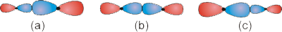
6.5-11. Constructing the MO's for a Three-Atom System
- Viewing the Video
-
•View the video in this window by selecting the play button.
-
•Use the video controls to view the video in full screen.
-
•View the video in text format by scrolling down.

Figure 6.26
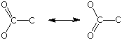
6.5-12. SO2
The structural features that could only be explained by invoking resonance in Chapter 5 are readily understood in terms of delocalized MO's. Consider the case of SO2 shown in Figure 6.27. Although the bond angles are 120° not 180°, the atomic orbitals are p orbitals not s orbitals, and the interactions are pi not sigma, the relative phases of the AO's are the same for SO2 as for the three-atom system discussed above. Two resonance structures (shown at the top of the figure) were used to account for the fact that the two S-O bonds are of equal length. The two structures differ in the position of the π bond, which is shared between the two bonds, and the location of one of the lone pairs, which appears to be shared by the oxygen atoms. The σ bonds and the lone pairs except the one that appears in different locations in the Lewis structure lie in the molecular plane and will be ignored in the following MO description discussion, which centers on the π system. Note that the term resonance is not required in the MO description. The π system contains four electrons: the two in the π bond and two in the lone pair that appears to move in the two resonance forms. The AO's used to construct the π MO's are p orbitals that are perpendicular to the molecular plane. Placing four electrons into the system fills the π and n (nonbonding) orbitals. Note that there is one bonding orbital (the π bond) and one lone pair (nonbonding orbital) as shown in the Lewis structures. However, the π bond is delocalized over all three atoms, with no difference between the two S-O bonding regions, and the lone pair is delocalized over both oxygen atoms. Thus, all of the features that caused us to invoke resonance with the earlier bonding theory are explained with molecular orbital theory.
Figure 6.27: π MO's for Sulfur Dioxide
(a) Viewing the p orbitals from the side; (b) Viewing the p orbitals from above so that only the top of the p orbitals can be seen; (c) Energy diagram showing two occupied MO's and identifying the HOMO and LUMO.
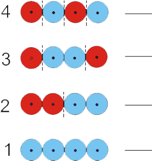
6.5-13. Orbital Types in a Delocalized Four-Atom System - Exercise
Exercise 6.13:
Use the MO diagram in the figure to determine the number of bonding interactions, the number of antibonding and orbital type for each of the four MO's of a delocalized four-atom system.
Orbital Number 4:
bonding interactions
0_0__
There are no pairs of adjacent orbitals with the same phase, so there are no bonding interactons.
antibonding interactions
3_0__
There are three changes in phase, so there are three antibonding interactions.
-
orbital type:
-
bonding There are more antibonding interactions than bonding interactions, so this is an antibonding orbital.
-
antibonding
-
nonbonding There are more antibonding interactions than bonding interactions, so this is an antibonding orbital.
Orbital Number 3:
bonding interactions
1_0__
here is one pair of adjacent orbitals with the same phase, so there is one bonding interacton.
antibonding interactions
2_0__
There are two changes in phase, so there are two antibonding interactions.
-
orbital type:
-
bonding There are more antibonding interactions than bonding interactions, so this is an antibonding orbital.
-
antibonding
-
nonbonding There are more antibonding interactions than bonding interactions, so this is an antibonding orbital.
Orbital Number 2:
bonding interactions
2_0__
There are two pairs of adjacent orbitals with the same phase, so there are two bonding interactons.
antibonding interactions
1_0__
There is one one phase change between adjacent atoms, so there is one antibonding interaction.
-
orbital type:
-
bonding
-
antibonding There are more bonding interactions than antibonding interactions, so this is a bonding orbital.
-
nonbonding There are more bonding interactions than antibonding interactions, so this is a bonding orbital.
Orbital Number 1:
bonding interactions
3_0__
There are three pairs of adjacent orbitals with the same phase, so there are three bonding interactons.
antibonding interactions
0_0__
There are no changes in phase, so there are no antibonding interactions.
-
orbital type:
-
bonding
-
antibonding There are more bonding interactions than antibonding interactions, so this is a bonding orbital.
-
nonbonding There are more bonding interactions than antibonding interactions, so this is a bonding orbital.
Assume a four-electron system to identify the orbital number of the HOMO and LUMO.
HOMO
2_0__
The four electrons would enter as two pairs in the lowest two orbitals, so orbital 2 is the occupied orbital that is highest in energy, i.e., the HOMO.
LUMO
3_0__
The four electrons would enter as two pairs in the lowest two orbitals, so orbital 3 is the unoccupied orbital that is lowest in energy, i.e., the LUMO.
6.5-14. Four-atom Example: Butadiene
The Lewis structure of butadiene (Figure 6.28) shows two C=C double bonds and one C-C single bond, so we would expect two bond lengths of about 130 pm and one of about 150 pm. Experimentally, we find that there are two bonds of 134 pm and one of 135 pm, the approximate length of a C=C double bond. We now use an MO treatment of the π system to explain this observation. The relative phases of the p orbitals are the same as the s orbitals in the above exercise. Figure 6.28a views the molecule from the top so that only the top lobe of each orbital is shown, while Figure 6.28b shows the side-on view. There is one electron in each p orbital, so there are a total of four electrons in the π system, which are distributed into MO's as shown. Note that both pairs of electrons reside in π bonding orbitals, which is consistent with the two double bonds predicted by the Lewis structure. However, the π orbitals are delocalized over all four carbon atoms not localized between two atoms as shown in the Lewis structure, which explains why the bond lengths are nearly the same.
Figure 6.28: MO's for Butadiene
(a) The circles represent the relative phases of the p orbitals (the orbitals viewed from the top). (b) Each p orbital represented by the traditional 'figure 8'.
6.5-15. Benzene
As our last example, we examine the delocalized π system in benzene (C6H6) shown in Figure 6.29. Recall that the double bonds in benzene are sometimes represented by a circle in Figure 6.8 due to resonance in the molecule. Although the construction of the MO's is beyond the scope of this text, an examination of them demonstrates the rules for construction and provides a better understanding of the bonding in this very important molecule. There are six carbon atoms and six p orbitals, so there are six π MO's. The lowest energy MO has no nodal planes and is a bonding orbital delocalized over all six atoms. The highest energy orbital has a nodal plane between each pair of atoms, but, due to the symmetry of benzene, this requires only three nodal planes. Thus, the four remaining MO's must contain either one or two nodal planes. In fact, two MO's have one nodal plane, and two MO's have two nodal planes. The π system has six electrons, so only the three bonding MO's are occupied, which gives rise to the three double bonds in the Lewis structure. The three MO's are delocalized over all six carbon atoms, so, consistent with representing the double bonds with a circle, the π electron density is spread over the entire molecule with no localized double bonds.
Figure 6.29: MO's for the π System of Benzene