
Lab 3 - Capacitors
Introduction
The basic function of a capacitor is to store charge and thereby electrical energy. This energy can be retrieved at a later time for a variety of uses. Often, multiple capacitors are combined together to form a single circuit. There are two fundamental ways of connecting capacitors together: in series and in parallel. In this lab, you will explore how charge and energy are stored on both series and parallel combinations of capacitors.Discussion of Principles
A capacitor is a set of two metal conductors separated by a small distance. Usually some type of dielectric (non-conducting) material is placed between the two conductors. An example is the parallel plate capacitor shown in Fig. 1. When connected to a voltage source, such as a battery, the two conducting plates become charged. When the battery is first connected, free electrons inside the top capacitor plate will move toward the positive terminal of the battery. This continues until the top capacitor plate is at the same potential as the positive terminal of the battery. A net positive charge, +Q, will then be on the top capacitor plate. At the same time, free electrons inside the wire connecting the negative terminal to the bottom capacitor plate will move toward the bottom capacitor plate. This continues until the bottom capacitor plate is at the same potential as the battery's negative terminal. A net negative charge, –Q, will be present on the bottom capacitor plate.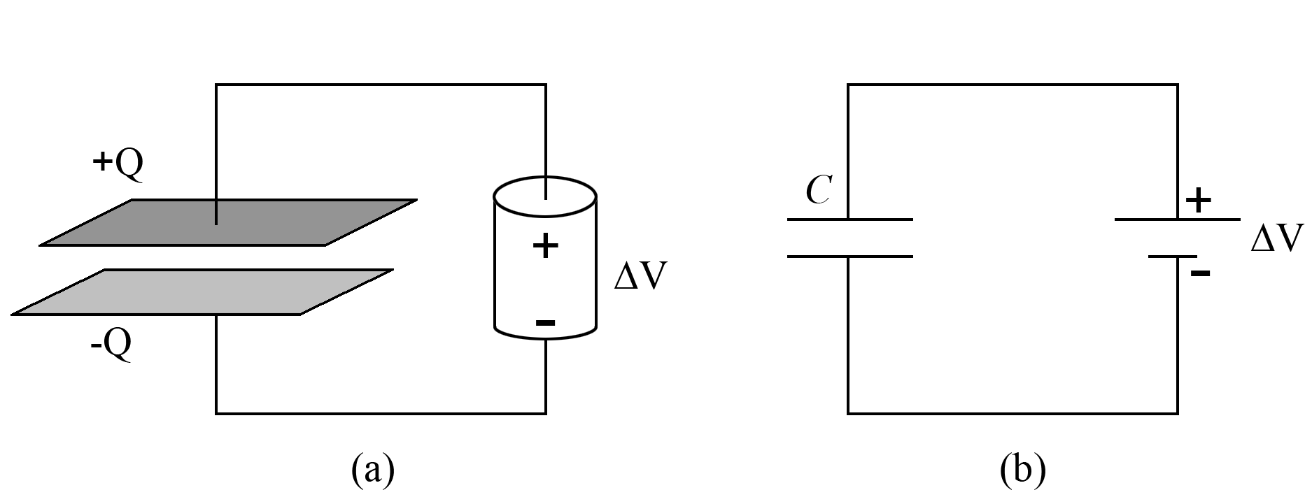
Figure 1: Capacitor circuit
ΔV
across the terminals of the battery. The amount of charge deposited on a capacitor is directly proportional to the potential difference placed across its plates. This can be written as
( 1 )
Q = CΔV
( 2 )
E =
C(ΔV)2.
| 1 |
| 2 |
Q = CΔV
, this formula can be rewritten in the two other equivalent forms
( 3 )
E =
·
| 1 |
| 2 |
| Q2 |
| C |
( 4 )
E =
QΔV.
| 1 |
| 2 |
Capacitors Connected in Parallel
Frequently, we want to combine multiple capacitors into one circuit. One way to combine capacitors is to connect them in parallel as shown in Fig. 2. Note that the top plates of both capacitors are connected to the positive terminal of the battery, and the bottom plates of both capacitors are connected to the negative terminal. Therefore, the potential difference across each individual capacitor will be the same as the total potential difference placed by the battery across the whole parallel arrangement.( 5 )
ΔV1 = ΔV2 = ΔV
( 6 )
Qtotal = Q1 + Q2.

Figure 2: Sketch and schematic of two capacitors in parallel arrangement
Ctotal,
will be different from either of the individual capacitances, C1 or C2. To determine this equivalent capacitance, first note that we can use Eqs.(1)Q = CΔV
and (5)ΔV1 = ΔV2 = ΔV
to write Qtotal = CeqΔV,Q1 = C1ΔV, and Q2 = C2ΔV.
Substituting these expressions into Eq. (6)Qtotal = Q1 + Q2.
and canceling the common factor of ΔV,
we get
( 7 )
Ctotal = C1 + C2.
Ceq.
So for a parallel arrangement made up of N different capacitors, Ceq = C1 + C2 + C3 + ... + CN.
The energy Etotal
stored in the parallel arrangement can be calculated using Eq. (2)E =
C(ΔV)2.
as
| 1 |
| 2 |
( 8 )
| Etotal | = |
| ||||
| = |
| |||||
| = |
|
Capacitors Connected in Series
Another way to combine capacitors is to connect them in series as shown in Fig. 3. When connected to a battery, the bottom plate of the first capacitor C1 will store a charge –Q and the top plate of the second capacitor C2 will store a charge +Q. We see then that the total charge placed on the overall series arrangement by the battery is Q. Notice that the top plate of C1 and the bottom plate of C2 are connected by a conducting wire, forming a single H-shaped conductor. This conductor is not connected to the battery, so the battery cannot directly provide charge to it. Instead, the negative charge –Q on the bottom plate of C1 and the positive charge +Q on the top plate of C2 will cause free electrons in the H-shaped conductor to move to the top. The result is an induced net charge of +Q on the top plate of C1 and an induced net charge of –Q on the bottom plate of C2. Therefore, both capacitors will have the same charge Q, which is the same as the total charge on the entire arrangement.( 9 )
Qtotal = Q1 = Q2
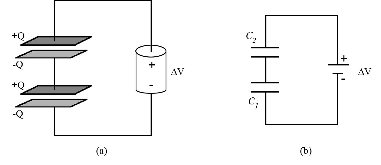
Figure 3: Sketch and schematic of two capacitors in series arrangement
ΔV2.
Then, moving from the top plate to the bottom plate of C1, the potential will drop by ΔV1.
The potential difference ΔV
across the entire series arrangement is equal to the sum of the potential differences across each individual capacitor.
( 10 )
ΔV = ΔV1 + ΔV2
Q = CΔV
to write the potential difference across the individual capacitors and the parallel arrangement as the following.
( 11 )
ΔV =
| Qtotal |
| Ceq |
( 12 )
ΔV1 =
| Qtotal |
| C1 |
( 13 )
ΔV2 =
| Qtotal |
| C2 |
ΔV = ΔV1 + ΔV2
, using Eq. (9)Qtotal = Q1 = Q2
, and canceling the common factor, Qtotal,
gives
( 14 )
| 1 |
| Ceq |
| 1 |
| C1 |
| 1 |
| C2 |
E =
QΔV.
,
| 1 |
| 2 |
( 15 )
| Etotal | = |
| ||||
| = |
| |||||
| = |
|
| Parallel Arrangement | Series Arrangement | |||||||
| ΔV = ΔV1 = ΔV2 | ΔV = ΔV1 + ΔV2 | |||||||
| Qtotal = Q1 + Q2 | Qtotal = Q1 = Q2 | |||||||
| Ceq = C1 + C2 |
| |||||||
| Etotal = E1 + E2 | Etotal = E1 + E2 |
Objective
The objective of this experiment is to study the characteristics of capacitors in series and parallel arrangements and to qualitatively investigate the energy stored in such arrangements.Equipment
- Signal interface with power output
- DataStudio software
- Multimeter
- Capacitance meter
- Two different capacitors
- One LED
- Stopwatch
Procedure
Please print the worksheet for this lab. You will need this sheet to record your data.
Caution:
Before connecting the power supply to the circuit, ask your TA to check your circuit connections to make certain that your capacitors are connected correctly.
Before connecting the power supply to the circuit, ask your TA to check your circuit connections to make certain that your capacitors are connected correctly.
Procedure A: Lighting an LED
1
Open the appropriate DataStudio file associated with this lab. The screen should contain a signal generator window similar to the one shown in Fig. 4.
2
In the signal generator window select DC.
In the DC voltage field, type 5.0.
Click ON.
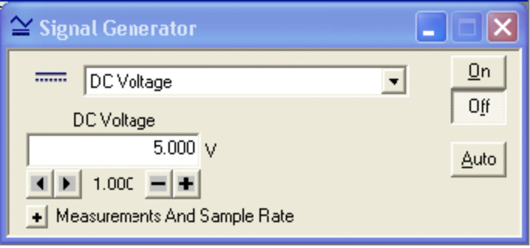
Figure 4: Signal generator window
3
Discharge both of your capacitors by shorting them out for at least 10 seconds as shown in Fig. 5.
You can check to see if the capacitors are fully discharged by using the voltmeter to read the potential difference across each capacitor. See Appendix K.
The readings should be very close to 0.0 volts.
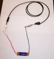
Figure 5: Discharging a capacitor
4
Connect the two capacitors in series. They must be connected so that the arrows printed on each capacitor are facing the same direction as shown in Fig. 6.
The red output lead must be connected to the notched end of one capacitor (this is also the end with the black face) while the black lead must be connected to the end that has the arrows pointing toward it (this is the end with the silver face). This will charge the capacitors.
Caution:
An incorrectly connected capacitor will get very hot!
An incorrectly connected capacitor will get very hot!
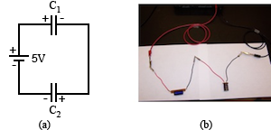
Figure 6: Circuit diagram and photo of capacitors in series
5
Disconnect the power output from the circuit by removing the red and black leads from the capacitors. DO NOT turn off the power output or set its voltage to zero.
6
Connect the LED to the capacitor arrangement as shown in Fig. 7.
The red and black LED leads should be connected the same way the red and black power amplifier leads were connected.
Immediately begin timing how long the LED remains lit. Record the time on the worksheet.
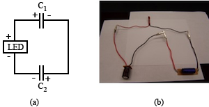
Figure 7: Circuit diagram and photo for LED connection
7
Disconnect your series arrangement, and fully discharge both capacitors.
8
Connect the two capacitors in parallel. Again, the arrows should point in the same direction as shown in Fig. 8.
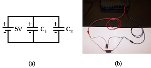
Figure 8: Circuit diagram and photo of capacitors in parallel
9
Repeat steps 3 through 6 for the parallel arrangement referring to Fig. 8. Record the time for the parallel arrangement on the worksheet.
10
Now use just the 1000-µF capacitor and see how long the LED remains lit. Record this time on the worksheet.
Checkpoint 1:
Ask your TA to check your work before proceeding.
Ask your TA to check your work before proceeding.
Procedure B: Capacitors in Parallel
11
Set the capacitance meter to the appropriate setting.
Measure the capacitance of each individual capacitor. Record the capacitances in Data Table 1.
When measuring capacitance, the uncertainty is ±5% of the displayed value.
12
Connect the two capacitors in parallel.
13
Using the capacitance meter, measure the total (or equivalent) capacitance of the parallel arrangement. Record this value in Data Table 1.
14
Leave the parallel arrangement connected and discharge the capacitors by shorting them out one at a time.
15
Use the multimeter to make sure they are fully discharged. See Appendix K.
16
Connect the parallel arrangement to the power output leads as shown in Fig. 8.
17
Turn the multimeter on and switch to the proper DC voltage scale.
For this multimeter, the uncertainty in the potential difference is
±1% of the displayed value.
18
For this step, it is important that you do not touch the capacitor leads when you are measuring the voltage. You are a resistor, just like the LED, so you are capable of discharging the capacitor by touching it.
Measure and record the potential difference ΔV1 and ΔV2
across C1 and C2, respectively. Record these values in Data Table 1.
19
Measure the potential difference ΔVp
across the parallel arrangement, and record this in Data Table 1.
20
Using the measured values of capacitance and voltage and Eq. (1)Q = CΔV
, calculate the charges and associated uncertainties for the individual capacitors and the parallel arrangement. Record these values in Data Table 1.
21
Using Eqs. (2)E =
C(ΔV)2.
and (8)| 1 |
| 2 |
| Etotal | = |
| ||||
| = |
| |||||
| = |
|
22
Using Eq. (7)Ctotal = C1 + C2.
, calculate the theoretical equivalent capacitance and the theoretical uncertainty for the two capacitors in parallel. Record this value in the worksheet.
23
Calculate the percent difference between the theoretical value and the measured value (see Data Table 1) of the equivalent capacitance. See Appendix B.
24
Using Eq. (6)Qtotal = Q1 + Q2.
, calculate the theoretical total charge and its associated uncertainty for the two capacitors in parallel. Record this value on the worksheet.
25
Calculate the percent difference, between the theoretical value and the measured value of the total charge, and record this on the worksheet.
Checkpoint 2:
Ask your TA to check your table and calculations.
Ask your TA to check your table and calculations.
Procedure C: Capacitors in Series
26
Record the previously measured capacitances of the two capacitors in Data Table 2.
27
Connect the two capacitors in series.
28
Using the capacitance meter, measure the total capacitance of the series arrangement. Record this value in Data Table 2.
29
Leave the series arrangement connected and discharge the capacitors by shorting them out one at a time. Make sure they are fully discharged.
30
Connect the power amplifier to the arrangement as shown in Fig. 6.
31
Measure the voltage across each individual capacitor. Record your measurements in Data Table 2. Again, be careful not to touch the leads when recording the voltages.
32
Measure the voltage ΔVs
across the entire series arrangement. Record this value in Data Table 2.
33
Using the measured values of capacitance and voltage, calculate the charge stored on each capacitor and the associated uncertainties. Record these values in Data Table 2.
34
Using measured values for the total capacitance and voltage and Eq. (1)Q = CΔV
, calculate the charge in the series arrangement, and record these values in Data Table 2.
35
Using Eqs. (2)E =
C(ΔV)2.
and (15)| 1 |
| 2 |
| Etotal | = |
| ||||
| = |
| |||||
| = |
|
( 16 )
σCeq = Ceq2
 |
|


36
Calculate the theoretical capacitance and its uncertainty for the series arrangement using Eq. (14)| 1 |
| Ceq |
| 1 |
| C1 |
| 1 |
| C2 |
37
Calculate the percent difference between the theoretical value and the measured value (from Data Table 2) of the equivalent capacitance, and record this on the worksheet.
38
Using Eq. (10)ΔV = ΔV1 + ΔV2
, calculate the theoretical voltage and its uncertainty for the series arrangement. Record this value on the worksheet.
39
Calculate the percent difference between this theoretical value and the measured value (from Data Table 2) of the total voltage and record this on the worksheet.
Checkpoint 3:
Ask your TA to check your table and calculations.
Ask your TA to check your table and calculations.