
Lab 6 - Force on a Wire
Introduction
A stationary or moving electric charge will experience a force when placed in an electric field. On the other hand, an electric charge has to be moving to experience a force due to a magnetic field. A current in a wire is due to moving electrons. Therefore, a current-carrying wire will experience a force when placed in a magnetic field. Measuring the force exerted by a magnetic field on the wire with a known current flowing through it offers one method to determine the strength of the magnetic field.Discussion of Principles
The force exerted by a magnetic fieldB
on a short, straight wire of length L
that carries a current I
is given, using a cross product, by the vector equation
( 1 )
F = IL × B
= IL × B L
is a vector whose magnitude is equal to the length of the wire and whose direction is the same as the direction of the current. The magnitude of the force is given by
( 2 )
F = ILB sin θ
L
and B.
In this experiment, the angle between . L
and B
will always be 90°, so
( 3 )
F = ILB.
A
and the middle finger in the direction of the second vector B
to get the cross product C = A × B
in the direction of the thumb. See Fig. 1 below.
In the case of Eq. (1) = A × B F = IL × B
, the forefinger would point in the direction of = IL × B L
or the current and the middle finger would point in the direction of the magnetic field. The thumb will give the direction of the force.
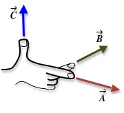
Figure 1: Right-hand rule
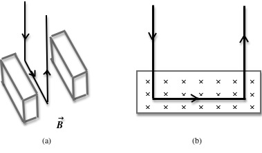
Figure 2: Two views of a rectangular loop in a magnetic field
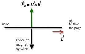
Figure 3: Force diagram
Objective
The objective of this experiment is to determine the magnitude of the magnetic field by measuring the force experienced by a current-carrying wire placed in this magnetic field.Equipment
- Magnet assembly
- Digital balance
- Rectangular loop of wire of multiple turns
- Ring stand
- Power source
- Multimeter
- PASCO RLC Circuit board
- Meter stick
- Connecting wires
- DataStudio software
Procedure
Please print the worksheet for this lab. You will need this sheet to record your data.
1
Open the DataStudio file associated with this lab, which starts the DataStudio program. A screen similar to Fig. 4 is displayed.
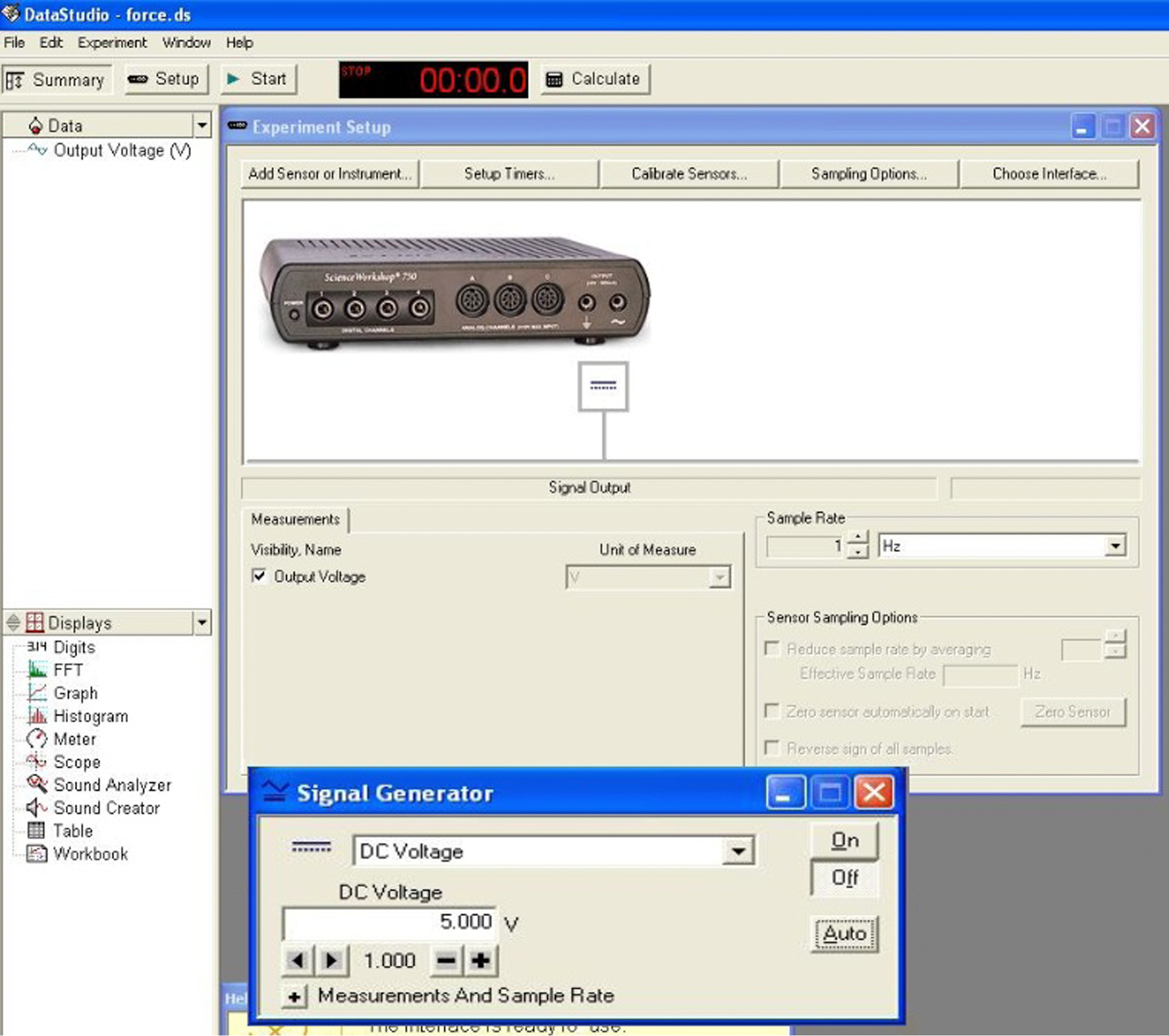
Figure 4: Screenshot of DataStudio file
2
Turn on the digital balance and wait for the display to read zero grams. Then carefully place the magnet assembly on the measuring pan.
Dropping the magnet on the measuring pan will permanently damage the scale.
3
Measure the mass of the magnet and record this value on the worksheet.
4
Attach the main unit to the ring stand so that the lever arm can swing upward from horizontal.
5
Attach a current loop to the end of the main unit.
6
Position the equipment so that the current loop extends into the top notch of the magnetic assembly without touching the sides or the bottom. See Fig. 5.
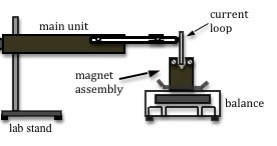
Figure 5: Side-view of apparatus
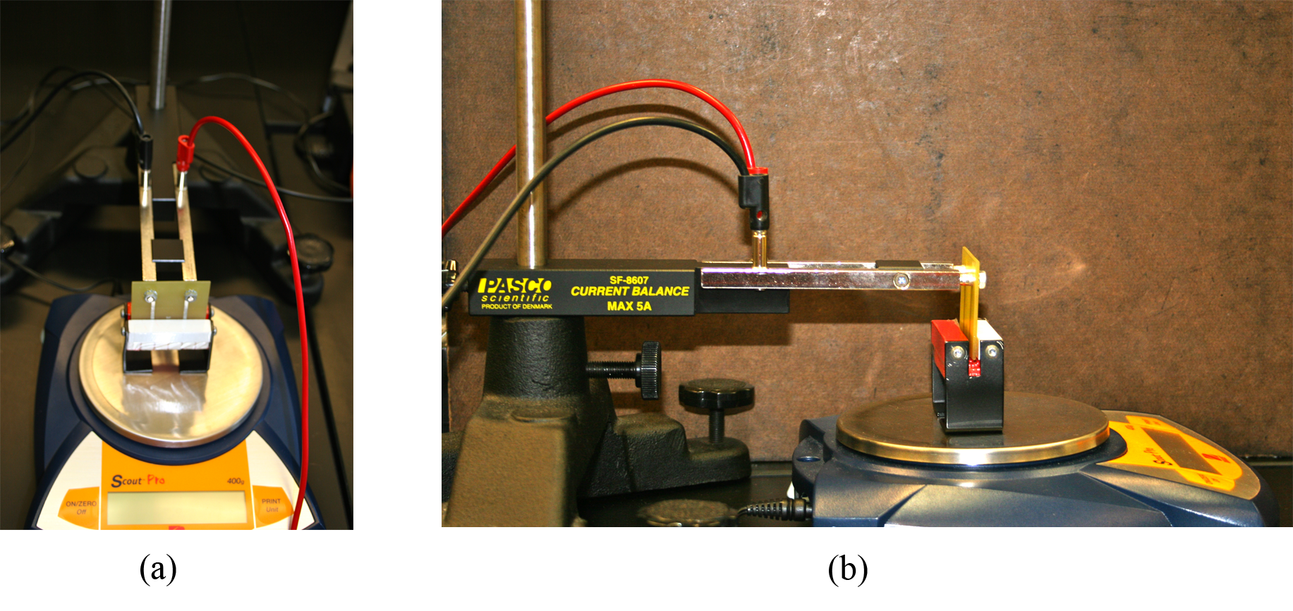
Figure 6: Photo of front and side view of experimental set-up
7
Make the circuit connections as follows:
-
•Connect the positive terminal of the power output of the interface to the 10-ohm resistor located on the PASCO RLC circuit board.
-
•Connect the other resistor terminal to an arm of the main unit.
-
•Connect the remaining arm of the main unit to a multimeter that will serve as an ammeter.
-
•Then connect the second terminal of the ammeter back to the negative terminal of the power output. This will complete your circuit. Your circuit should now look like Fig. 7.
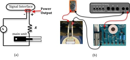
Figure 7: Circuit diagram
Checkpoint 1:
Ask your TA to check your circuit before proceeding.
Ask your TA to check your circuit before proceeding.
Procedure A: Force versus Length
You will be using current loops of 37, 38, 39, and 40 for this part of the experiment. Fig. 8 shows examples of three of these current loops.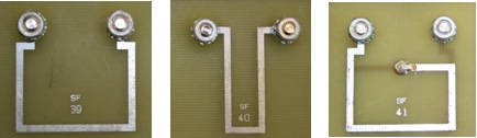
Figure 8: Photo of three different current loops
8
Measure and record the length of each wire. Think about what part of the current loop you should measure. Record this length and its uncertainty on the worksheet.
9
Make sure that the AUTO button is active in the signal generator window, not the ON button. See Fig. 9.
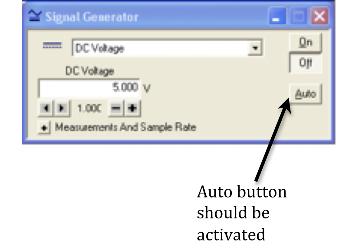
Figure 9: Signal generator window
Current will begin flowing when you click START and stop flowing after 10 seconds or when you click STOP. This will ensure that the resistor does not overheat in between measurements.
10
Extend the edge of the current loop into the magnet assembly. Supply a current of about 0.3 amps to the circuit by increasing the voltage to 5 volts in the signal generator window.
11
Click START and record the current and the new value for the mass in Data Table 1.
12
Repeat steps 10 and 11 for all four loops.
13
Complete Data Table 1 on the worksheet.
14
Calculate the average current applied to the loops and the standard deviation in the average current. See Appendix E.
15
Using Excel, plot a graph of force versus length. See Appendix G.
16
Use the linest function in Excel to calculate the slope and its uncertainty. See Appendix J.
Enter these values on the worksheet.
17
Write down the formula for the uncertainty in B in terms of the uncertainties in slope and average current. See Appendix C.
18
Calculate the magnitude of B and its uncertainty from the slope and enter this value on the worksheet.
19
Calculate the percent uncertainty in the value of B. See Appendix B.
Checkpoint 2:
Ask your TA to check your table values and graph.
Ask your TA to check your table values and graph.
Procedure B: Force versus Current
20
Use the current loop labeled SF 38.
21
Vary the current to span 5 values between –0.3 amps and 0.3 amps by adjusting the voltage on the signal generator window.
22
Click START and record the absolute mass for each of the five current values.
23
Complete Data Table 2 on the worksheet.
Be sure to use the correct sign for the force on the wire.
24
Using Excel, plot a graph of force versus current.
25
Use the linest function in Excel to calculate the slope and its uncertainty. Enter these values on the worksheet.
26
Write down the formula for the uncertainty in B in terms of the uncertainty in the slope and average current. See Appendix C.
27
Calculate the magnitude of B and its uncertainty from the slope and enter this value on the worksheet.
28
Determine the percent uncertainty in the value of B.
29
Determine the percent difference between the values for B calculated in Procedures A and B.
Checkpoint 3:
Ask your TA to check your table values and graph.
Ask your TA to check your table values and graph.