
DC Circuits–Series, Parallel, and Combination Circuits
Purpose
-
•To investigate resistors wired in series and parallel as well as combinations of the two.
-
•To examine how current behaves at junction points in a circuit and how its flow is influenced by circuit resistances and emfs.
-
•To study how power is affected by current, voltage, and resistance.
-
•To study the effect of the internal resistance of a battery on the power available to a circuit.
-
•To study the behavior of series-parallel combinations of resistors and learn how to analyze them using equivalent resistance.
Equipment
- DC Circuits Apparatus
- Pencil
Simulation and Tools
Open the DC Circuits Apparatus simulation to do this lab.Explore the Apparatus
The large blue area with the small dots (circles) is a circuit board where we'll create our circuits.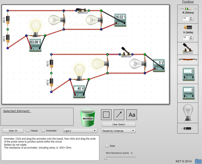
Figure 1: DC Circuits Apparatus
1
Drag one of each type of circuit element onto the circuit board.
Notice that they won't go just anywhere. They want their little blue and green ends to attach to the little dots. There's no significance to the dots. They just help us align things in a pleasing way. But the blue and green ends are significant because they are the only place where circuit elements can be connected. For example, the wires are insulated everywhere except at their blue and green ends. The circuit boards in your computer have a similar layout. They have actual holes in them that allow you push the ends of the elements through to solder them to flat wires attached to the bottom of the board.
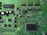
Figure 2: Circuit Board
2
Notice that you have your choice of dragging, stretching/shortening, or rotating each type of element. How do you drag, stretch/shorten, or rotate an element? I'll give you the first one to get you started.
-
aYou drag an element by clicking on the body of the element and dragging it.
-
bYou stretch or shorten wires, batteries, and resistors by .
-
cYou rotate wires, batteries, and resistors by .
3
Let's create your first circuit. Using all but two of the elements on your circuit board, create the circuit in Figure 3a. Use the default 15-Ω resistor and the default 10-V battery.
4
How do you open and close the circuit using the switch?
5
If you click and drag one of the meters, the meter wires disconnect from the circuit. What happens if you hold down the Shift key while clicking and dragging the meter?
6
The (conventional) current is indicated by the little moving dots. According to our definition of current, which end of the battery is the positive end? (black or gold)
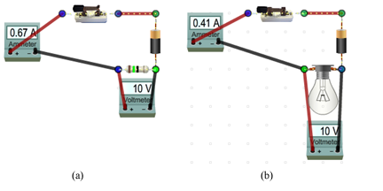
Figure 3: (a) Simple DC Circuit (b) Simple Circuit with Bulb
7
Without pressing the Shift key, pull the ammeter away from the circuit to disconnect it. Now reconnect it but swap the connections to the circuit. What happens and how do you interpret the meaning of the change? (Just do your best.)
Our digital meters are not damaged by this backwards connection but analog meters (with rotating needles) can be. So as a general practice, care should be taken when attaching meters.
8
Finish this general rule below about how meters are connected.
- The circuit should be wired so that the current enters the terminal of any meter it encounters.
9
Reconnect the ammeter as in Figure 3a.
If you drag the switch, wire, or battery out of the circuit, the current will cease to flow because current will only flow around a complete circuit. That is, one with no gaps in it. What about the meters? Experiment a bit to answer the following.
- If you remove the ammeter from the circuit, you find that the current . Thus, we know that a current must flow through an ammeter. To insert an ammeter into a circuit, the circuit must be opened. The ammeter then fills in the gap created. An ammeter measures the current flowing through itself.
10
How about the voltmeter? The current arriving at the junction on the left side of the resistor has a choice of two paths. It can go through the resistor or the voltmeter or both. Remove the resistor first, then replace it and remove the voltmeter. Look carefully at the current dots and the ammeter each time.
- A voltmeter is connected across a circuit element. That is, it's attached to each end of the circuit element. Most of the current flows through the with a negligible amount going through the . The smaller the proportion of the current that flows through it, the better the voltmeter.
11
Circuit elements are inserted into a circuit to produce certain desired results. Let's see how that works. First, let's record some initial values. Record the initial current and the voltage drop.
12
Now let's replace the resistor with an upside down bulb. Just drag the resistor off to the side. Make room for the bulb by Shift+dragging the voltmeter down a little. Now bring on a bulb, rotate it 180°, and put it where the resistor was. Record your new meter readings with the bulb.
13
That's not much light. Or is it glowing at all? To test, drag the battery away from its contacts and then bring it back. You should see the small change in brightness. We need a "bigger" battery. Click on the battery in the circuit. Below the circuit board, you'll see a text box showing that the battery voltage is 10 V. There is a numeric stepper beside it that you can use to adjust the voltage up to a maximum of 60 V. (Variable voltage batteries don't really exist.) You can also just type in a number, but use the stepper to gradually increase the battery voltage up to 60 V. Just hold down the up arrow and notice the change in brightness (power).
Note:
If you set a resistance or voltage value by typing in a number, you must then hit Enter to set the new value.
If you set a resistance or voltage value by typing in a number, you must then hit Enter to set the new value.
Record your new meter readings with the 60-V battery.
14
OK, that looks better. This bulb seems to be designed for 60 volts. But suppose we'd like to dim it for a romantic dinner. We could switch batteries again, but that would be a nuisance. Let's add a variable resistor. (Actually, all our resistors are variable. And variable resistors do exist. You own a lot of them.) Remove the short wire at the top, beside the switch, and replace it with a resistor. Click on the resistor and then increase its resistance using the numeric stepper below the circuit board. You should see the bulb dim.
15
So what's with the numeric steppers in the Toolbox and below the circuit board? The ones in the toolbox preset the voltage or resistance of a battery or resistor that you then want to drag onto the circuit board. The ones below the circuit board change these values for a battery or resistor that you select on the circuit board by clicking on it. The ones in the toolbox set the values for a battery or resistor that you will then drag onto the circuit board.
Series and Parallel Circuits
Consider the "life" of an electron in your car's electrical system. Each time it leaves the negative pole of your car battery, it has a bewildering variety of routes to choose from. Just in your radio alone, there are many routes it might take before it returns to the battery. This complex arrangement allows each component of the electrical system to get just the current it needs. The analysis of such complex systems is beyond the scope of an introductory physics class, but many of the principles involved can be discovered using simple batteries, resistors, bulbs, and meters. By observing the brightness (Power = IV) of a simple bulb, we can learn how current and power are distributed in a complex circuit. The first part of this lab is an exploration. Your goal is to observe and organize your observations into models of the behavior of simple circuits. If you're working with a team, be sure to take turns doing the wiring. Feel free to go off the path. When you do, just be careful to avoid situations where current can flow through a path with little resistance, that is, one where there is no light bulb. Also, save your batteries by opening the circuit whenever you don't really need to see the bulbs glow. Well, not really. This is a virtual apparatus. You can't hurt it. But in a real circuit, shorting out a battery means you'll have to buy a new real one.Procedure
Please print the worksheet for this lab. You will need this sheet to record your data.
I. Explore Series, Parallel Circuits, and Combination Circuits
Let's explore and see what's ahead. The circuits you'll need, shown in Figure 4, are available in the "Pick a circuit" pull-down menu. Select "Four 3 Bulbs." The gap at the bottom of each circuit will be filled with a battery later.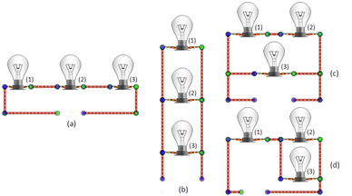
Figure 4: Three Bulbs Arranged Four Ways
A. Initial Observations
Let's make some observations. In what follows you'll be guided to make various observations, but you should be sure not to leave it at that. This apparatus provides you the opportunity to explore, develop your own models, and to do your own tests. After this activity, you should never look at a circuit diagram in a book or test and fail to "see" how it would behave.1
In each circuit in Figure 4, there are either two or three bulbs that are in electrically equivalent situations in that circuit. That is, with a battery (not yet present) in the circuit, they could swap positions with one another with no resulting change in their behavior. Record your predictions for each circuit.
-
aIn circuit (a), the bulbs that are in electrically equivalent situations are .
-
bIn circuit (b), the bulbs that are in electrically equivalent situations are .
-
cIn circuit (c), the bulbs that are in electrically equivalent situations are .
-
dIn circuit (d), the bulbs that are in electrically equivalent situations are .
2
Add 60-V batteries to circuit (a)–(d) in the gaps provided. The quickest way to create a 60-V battery is to adjust the selector under the battery in the Toolbox to sixty and then drag a battery to each of the circuits. Remember, the selectors in the Toolbox set the values for any resistor or battery that you subsequently drag onto the circuit board. The selector in the Selected Element box adjusts the value of the currently selected (glowing) resistor or battery.
You can clearly see that all the bulbs in circuits (b) and (c) are illuminated, but what about circuits (a) and (d)? Drag the battery in circuit (a) into and out of the circuit to confirm that the bulbs are slightly illuminated. Do the same for (d). Bulbs 2 and 3 in circuit (d) are pretty dim, but they're definitely on. The brightness of a bulb is an indication of the rate at which electrical energy is being converted to light energy. Heat is also generated in varying amounts depending on the efficiency of the bulb. The total rate at which the bulb is converting electric energy to light and heat is the power at which the bulb is operating. Newer bulb standards are designed to reduce the heat energy part of this equation. Could this mean the doom of the "Easy Bake Oven?"
Hopefully you selected 1, 2, and 3 in questions 1a and 1b and pairs in questions 1c and 1d.
3
For the ranking questions that follow, answer by using one of the symbols <, >, or = in each space.
-
aHow does the power dissipated (indicated by the brightness) of each bulb in circuit (a) compare?
- Pa1 Pa2 Pa3
-
bHow does the power dissipated (indicated by the brightness) of each bulb in circuit (b) compare?
- Pb1 Pb2 Pb1
-
cHow does the power dissipated (indicated by the brightness) of each bulb in circuit (c) compare?
- Pc1 Pc2 Pc3
-
dHow does the power dissipated (indicated by the brightness) of each bulb in circuit (d) compare?
- Pd1 Pd2 Pd3
4
We'll now replace our identical bulbs with resistors of three different resistances. Using the bulb numbering scheme from Figure 4, replace the bulbs as follows. That is, replace each bulb labeled (1) with a 20-Ω resistor, etc.
-
Bulb 1 → 20-Ω resistor
 (Red – Black – Black)
-
Bulb 2 → 30-Ω resistor
 (Orange – Black – Black)
-
Bulb 3 → 60-Ω resistor
 (Blue – Black – Black)
Notes:
-
1Ask your teacher if you are required to know resistor color codes. We won't address them further in this lab.
-
2Turn on "Values" and "Schematic" for alternate views. Leaving "Values" on is recommended.
-
3Don't forget to hit Enter after typing in numeric values.
-
4Please recycle your bulbs.

Be sure that all circuits are complete as evidenced by current flowing. You'll sometimes need to stretch the resistors.
B. Current
We'll first explore how the currents are determined by the circuit structure. We'll rely on the little moving current dots as an indicator of current flow. They're not perfect, but they do give a pretty good idea of what's happening. Their speed is proportional to the current through them.
1
How does the current through each resistor in circuit (a) compare? (Use the current dots as a guide.)
Ia1
Ia2
Ia3
2
How does the current through each resistor in circuit (b) compare? (Use the current dots as a guide.)
Ib1
Ib2
Ib3
3
How does the current through a resistor in circuit (a) compare to one in circuit (b)? (Use the current dots as a guide.)
Ia1,2,3
Ib1,2,3
4
From equation 2P = IV = I 2R =
, specifically, | V 2 |
| R |
P = I 2R,
you should see the reason for the large difference in the brightnesses of the bulbs in the two original bulb circuits. More current through a resistor or bulb means that it will dissipate more power. That is, more energy per time is converted to heat and light.
There's another thing that's different about the currents in circuits (a) and (b).
5
How does the current flowing through the battery in circuit (a) compare to the current through the battery in circuit (b)?
Ibattery a
Ibattery b
6
How does the current through the battery in circuit (a) compare to the current through a resistor in (a)?
Ibattery a
Iresistor a
7
How does the current through the battery in circuit (b) compare to the current through a resistor in (b)?
Ibattery b
Iresistor b
P = IV = I 2R =
, specifically, | V 2 |
| R |
P = IV,
you should see the price you pay for the bright bulbs in our original bulb circuit (b). The larger current will discharge the battery more quickly. Since the battery chemistry limits the total amount of charge that it can provide, the larger current will use up this charge in a shorter time (q = It)
in circuit (b).
Hopefully you observed that the current is the same throughout circuit (a). So,
This is the nature of a series circuit.
When circuit elements between two points are connected end to end with no branching, as in circuit (a), the current through each element is the same. This is called a series circuit.
8
Something entirely different is happening in circuit (b). Notice the current flowing up the left side of the circuit. Using our ranking system, we might say
Ibattery
Ibottom left wire
Imiddle left wire
Itop left wire.
9
So a relatively large current flows through the battery and part of it branches off to pass through each bulb. Let's improve on our simple "follow the current dots" estimation of the current by adding some meters and take some actual data for both circuits.
Edit circuit (a) to add three ammeters and a switch as shown in Figure 5. You may want to use the check boxes to turn on the "Values" of the resistors and batteries. Also, "Schematic" mode will help get you accustomed to circuit diagrams. But the pictorial view is a bit nicer to look at.
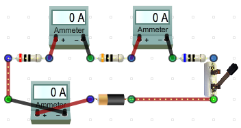
Figure 5: Current in Series
By the way, please try not to get attached to the meters. Their little flailing arms are right up there with cat videos but don't let them entice you to hook them up to every little node they pass. If you find yourself using terms like "adorable" just drag a few of them straight to the trash to desensitize yourself.
10
Close the switch and record the currents.
11
Making similar measurements in our parallel circuit (b) requires a bit more reorganization. Let's measure the current leaving the battery as well as the current through each bulb. We'll do this by dragging all three vertical wires on the left by two grid spaces to the left, and then insert ammeters in the gaps. We'll also replace the bottom right wire with an open switch.
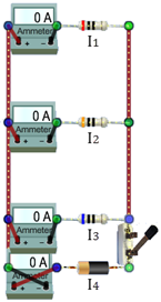
Figure 6: Current in Parallel
12
Close the switch and record the currents.
13
Based on these readings, what appears to be the relationship between the battery current and the currents in the resistors?
14
How about the currents in vertical side wires Ibot, Imid, and Itop in Figure 7? Since Ibot is the same as I4, we know that the current in the bottom left wire is 6 A. Enter that value in the blank under "Ibot =" in Figure 7.
15
You also know that the current in resistor 3 is 1 A. Record that value as I3 in Figure 7. How could you calculate the current Imid? Look at the moving dot current animation in each wire. Formulate a statement about the currents flowing into and out of a junction point (blue or green dot) such as the one to the left of resistor 3. Use words like "total," "into," "out of," and "sum of."
16
Use your statement to calculate Imid and Itop. Show your calculations. Use I1–4 from Figure 6 for the bulb currents.
Feel free to insert some meters to test and possibly revise your statement and calculations.
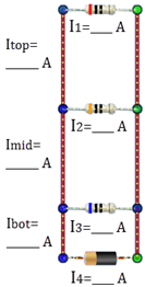
Figure 7: Current Readings
When multiple paths exist between two points in a circuit, as in circuit (b), the current divides at the first point and then recombines at the later point. This is called a parallel circuit. The current at the entering and exit points equals the sum of the currents in the branches.
Kirchoff's Point Rule:
The total current flowing into a point equals the total current flowing out of the point. or ΣIpoint = 0 where currents in are positive and currents out are negative.
The total current flowing into a point equals the total current flowing out of the point. or ΣIpoint = 0 where currents in are positive and currents out are negative.
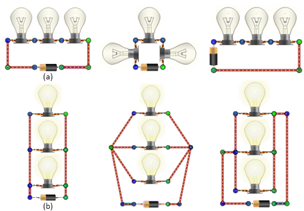
Figure 8: Equivalent Circuits
17
What about removing a resistor from a circuit? Suppose you removed resistor 2 from each circuit? Try it
18
The resistors in circuit (a) are connected in series. The resistors in circuit (b) are connected in parallel. Make a general statement about the effect of removing a bulb from each type of circuit. Specifically, what happens to the current through the remaining bulbs?
C. Voltage
Your results above should have confirmed that power increases with current. What about voltage? The "V" terms in equation 2P = IV = I 2R =
represent the voltage drop across a bulb or voltage increase across a battery. So we can now relate power dissipation by our resistors to voltage just as we did with current.
We don't have anything corresponding to the moving current dots to visually represent voltage changes so we'll need to start right away with voltmeters. Unlike ammeters, voltmeters don't require that you open a circuit to add them. Since they're simpler to work with, we'll look at both series and parallel circuits at the same time.
| V 2 |
| R |
1
Starting over with the "Four 3 bulbs" circuit, rebuild the series circuit (a) and the parallel circuit (b) by replacing bulbs 1–3 with 20 Ω, 30 Ω
, and 60 Ω, as you did earlier. Be sure to leave the switches open. (You'll have to switch to another circuit and then back to "Four 3 bulbs.")
2
Adding voltmeters is simple. Since they measure the change in voltage from one point to another, you'll need to attach one probe wire to each end of the resistor or battery you want to measure. The red wire will always connect to the end of the circuit element "closest" to the positive end of the battery. Figure 9 should help you see what that means.
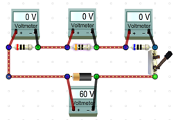
Figure 9: Voltage in Series
Hookup Hint:
If you drag a meter until it grabs the correct contacts and then Shift+drag the meter to where you want it, you'll be done in no time.
If you drag a meter until it grabs the correct contacts and then Shift+drag the meter to where you want it, you'll be done in no time.
3
In your investigation of current, you found the current to be the same everywhere in the series circuit. For the parallel circuit, the battery current equaled the sum of the currents in the three branches. What similar statement do you think will apply with voltages? How do you think the battery voltage will be related to the resistor voltage drops in each type of circuit? Make a statement about each type of circuit below. Use words like "total," "across," and "sum of."
4
Based on your statement, make a prediction before closing the switches. Above or below each voltmeter in Figures 9 and 10, write the approximate voltage reading you expect to find on that meter.
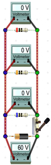
Figure 10: Voltage in Parallel
5
OK, close the switches. How'd you do?
| Series | Parallel | |
| Current | I = I1 = I2 = I3 | I = I1 + I2 + I3 |
| Voltage | V = V1 + V2 + V3 | V = V1 = V2 = V3 |
6
In circuit (c), bulbs
and
are connected in
, and this pair is connected in
with bulb
.
7
In circuit (d), bulbs
and
are connected in
, and this pair is connected in
with bulb
.
D. Resistance
In both the series and parallel circuits you've been working with, the individual resistances and battery voltages have been the same. But the result, the power dissipation by the individual resistors and bulbs, has been very different. Somehow the arrangement of the resistors in the two circuits has influenced the current flowing through them and the voltage drops across them.1
Clear the circuit board and build the circuits shown in Figure 11. Leave the bottom third of the circuit board empty for later use.
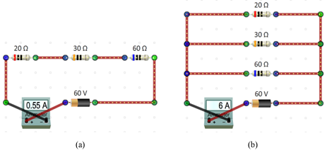
Figure 11: (a) Resistance in Series (b) Resistance in Parallel
The equivalent resistance, Req, is the single resistance that could replace a group of resistors and leave the rest of the circuit unaffected.
2
Add the identical circuits 12a and 12b below the first pair of circuits.
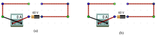
Figure 12: Equivalent Resistance
3
For each 3-resistor circuit in Figure 11, we want to find a single resistor that will result in the same current flowing through the battery when we place it in the matching circuit in Figure 12. That is, the current through the battery would be the same, 0.55 A, in Circuits 11(a) and 11(b). And the same current, 6 A, would flow through the battery in Circuits 12(a) and 12(b).
4
Where should we start? We have a 20, a 30, and a 60. Let's try the average resistance, 36.7 Ω. Place a 36.7-Ω resistor in each circuit in Figure 12.
5
Clearly this is not the "Goldilocks" resistance for either circuit. It was too small for the series circuit and too large for the parallel circuit. You should be able to use the resistance adjustment tool below the circuit board to adjust each resistor in Figure 12 until you return to the current flowing in the matching circuit from Figure 11. Record their values.
Ib =
, where Vb is the battery voltage.
| Vb |
| Req |
Ip = I1 + I2 + I3 Parallel Current
, we know that the current, Ib, in Circuit 11(b) must be
Ib = I20 Ω + I30 Ω + I60 Ω.
I20 Ω =
, and I30 Ω =
, and so on.
| Vb |
| 20 Ω |
| Vb |
| 30 Ω |
Ib = I20 Ω + I30 Ω + I60 Ω =
+
+
.
| Vb |
| 20 Ω |
| Vb |
| 30 Ω |
| Vb |
| 60 Ω |
| Vb |
| Req |
| Vb |
| 20 Ω |
| Vb |
| 30 Ω |
| Vb |
| 60 Ω |
| 1 |
| Req |
| 1 |
| 20 Ω |
| 1 |
| 30 Ω |
| 1 |
| 60 Ω |
| 1 |
| 10 Ω |
| Series | Parallel | |||||||||||
| Current | I = I1 = I2 = I3 | I = I1 + I2 + I3 | ||||||||||
| Voltage | V = V1 + V2 + V3 | V = V1 = V2 = V3 | ||||||||||
| Resistance | Req = R1 + R2 + R3 |
| ||||||||||
II. Case Studies with Series, Parallel, and Combination Circuits; Power
We'll now look at a few situations involving simple circuits.A. Internal Resistance, Terminal Voltage, and "Dead Batteries"
Everyone is familiar with the gradual dimming of a flashlight over time. Is this some sort of design feature to alert you when it's time to replace the batteries, or recharge them if they're rechargeable?1
Go ahead and build yourself a flashlight. Use a 60-V battery and don't forget the switch. No peeking at the figures! (Note: flashlights generally run on three to six volts. Ours are industrial strength.)
Adjust your flashlight to look something like Figure 13a. Hey! Don't laugh. When the headlight switch on my 1972 Mercury Capri ("The Sexy European") fell apart, I replaced it with a ceramic switch exactly like the one we're using to operate our flashlight. When I sold the car, the guy who bought it considered it an "interesting feature." And the blocks the car was sitting on kept the tires in top condition!
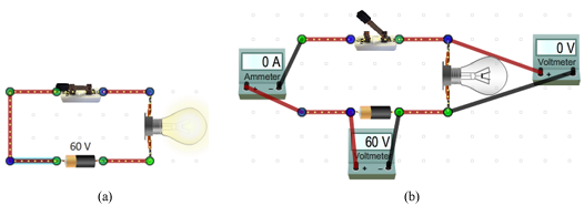
Figure 13: A Flashlight
2
Let's take our flashlight's "vitals." Add meters as shown in Figure 13b. Turn on your flashlight.
3
In Table 1, record the circuit current, I, the bulb voltage, Vbulb, and the battery emf,  .
.
4
Leave your flashlight on and (pretend to) go for a long walk—two or three hours at least.
5
OK, let's see how it's doing. Record your new readings in the "Later" row of Table 1.
6
Edit your figure to add a 1-Ω resistor in series with the battery as shown in Figure 14.
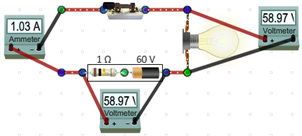
Figure 14: Internal Resistance of a Battery
7
The 1-Ω resistor represents the initial internal resistance of the new battery. It acts like a resistance in series with an ideal battery, but it can't really be separated from the battery since it's the materials that make up the battery that are resisting the current.
8
With the internal resistance set to 1 Ω, record the circuit current, I, the emf, the terminal voltage, Vt, and the voltage drop across the bulb, Vbulb, in Table 2.
9
Using equation 2P = IV = I 2R =
, calculate the following power values. Record these values in Table 3.
| V 2 |
| R |
-
aCalculate Pemf, the power provided by the battery emf, using the circuit current and the emf.
-
bCalculate Pir, the power dissipated by the internal resistance, using the circuit current and the internal resistance of the battery.
-
cCalculate Pbulb, the power dissipated by the bulb, using the circuit current and the voltage drop across the bulb.
-
dLeave Rbulb empty for now.
-
eCalculate the efficiency of this flashlight by calculating the percentage of the power supplied by the battery that's delivered by the bulb as heat and light.Efficiency =

Poutput by bulb Pprovided by the battery emf
× 100%.
10
Show your three power calculations and the efficiency calculation.
Kirchoff's Loop Rule:
Around any closed-circuit loop, the sum of the voltage drops equals the sum of the voltage rises.
Around any closed-circuit loop, the sum of the voltage drops equals the sum of the voltage rises.
| emf − Vir − Vbulb = 0 or | |
| emf − IRir − Vbulb = 0. | |
| 60.00 V − (1.03 A)(1.00 Ω) − 58.97 V = 0. |
11
Leaving our real flashlight running for a while lets a lot of ugly chemistry happen in the battery as previously discussed. The result will be an increase in the internal resistance, Rir. Change it to 50 Ω.
12
The result is pretty obvious. Let's check the numbers. Make the necessary readings and calculations to fill in the 50-Ω rows in Tables 2 and 3.
13
Show your three power calculations and the efficiency calculation.
14
There's one column in our data tables that we've neglected. We could have calculated the power dissipated by the bulb using I 2R
as we did with the internal resistance. But we didn't know the resistance of the bulb. But we now know the current and voltage drop across the bulb for each internal resistance. Calculate and record Rbulb for each trial.
15
Show your bulb resistance calculations.
16
Why did the bulb resistance decrease? Do a little research and see what you can come up with. The bulbs in this virtual apparatus are designed to behave like real bulbs. So just what is it that's affecting the bulb resistance?
B. Simplifying Circuits, Power Dissipation, Power Supplied by a Battery
In the circuit in figure 15, a 12-V battery supplies current to a network of four resistors. If this was a section of a circuit in your car hooked up to your car's 12-V battery, you might want to know what size fuse should be provided to protect it from overload. Or if the 1.0-Ω resistor represented a bulb, you might want to know the proper wattage of the bulb that should be used. Many students find solving this sort of problem perplexing. This is partly because it can be quite tedious and partly because without direct experience with circuits, it's difficult to see how to visualize a solution. We'll now look at two different circuits. We'll answer a few questions about each one, first using direct measurement from our lab simulations, and then using an algebraic technique that requires that you reduce the circuit step by step to its simplest form and then use these circuits to create the necessary equations to solve for unknowns. Circuit 1 Figure 15a will be our first circuit. The two tasks are listed below.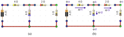
Figure 15: Compound Circuits
1
Clear your circuit board and build the circuit shown in Figure 15a. Create it in the top left corner of the circuit board and keep it small. Turn on "Values" so that you can see the resistor and battery values.
2
In Figure 15b, four labels, a–d, and three current arrows with labels I1–I3 have been added. Add these to your figure.
The current, I1, passes through the battery and the 4.0-Ω resistor. At point (b), it divides into currents I2 and I3. These rejoin at point (d) to become I1 again. Since I1 splits to produce I2 and I3, the current I1 would be the largest current in the circuit and the one we'd use to decide on the maximum current value of the fuse.
3
To find I1, you need to open the circuit in a part of the circuit where that current is flowing and insert an ammeter. Let's use the bottom-left wire to the left of point (d). Remove it and replace it with an ammeter. Record the current I1.
4
We don't have a power meter, but from equation 2P = IV = I 2R =
we know that we need either the current through this resistor or the voltage drop across it to find the power it dissipates. Insert meters into the circuit to measure each of these. Remember, an ammeter will replace a section of the circuit that carries the current you wish to measure, while a voltmeter will be attached across the resistor. Record your readings. Then remove the meters.
| V 2 |
| R |
5
Also calculate and record the power dissipated by the 1.0-Ω resistor.
6
There are three ways to calculate P1.0 Ω. Show all three calculations.

Note:
Figures 16–19 are used repeatedly in the discussion over the next several pages. To prevent the need for flipping back and forth to see the figures, they are also provided on a single page. You might want to use that copy when asked to add annotations to the figures.
Figures 16–19 are used repeatedly in the discussion over the next several pages. To prevent the need for flipping back and forth to see the figures, they are also provided on a single page. You might want to use that copy when asked to add annotations to the figures.
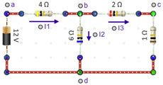
Figure 16: (same as 15(b))
7
Attach the negative lead of a voltmeter to point (d). Then attach the positive end to point (b) and record the voltage reading, Vbd. Then move the positive lead to point (c) and record the voltage reading, Vcd. Remove the meters.
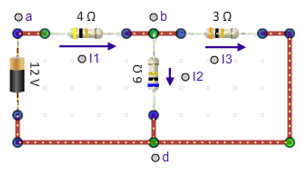
Figure 17
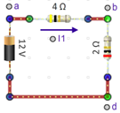
Figure 18
6.0 Ω
. This gives us our final equivalent circuit.
Figure 19
-
•determine the current supplied by the battery in order to select the proper fuse.
-
•determine the power dissipated by the 1.0-Ohm resistor, P1.0 Ω.
8
First, we want to determine the current supplied by the battery in order to select an appropriate fuse to protect the circuit.
We've called that current I1. I1 appears in all four circuits. The simplest place to find it would be Figure 19. The battery produces a potential difference Vad between points (a) and (d). From Figure 19, we know that the resistance between those two points is just 6.0 Ω. So with Ohm's Law, we can calculate the current I1.
| Vad | = | I1 × 6.0 Ω | ||||
| I1 | = |
| ||||
| I1 | = | 2.0 A |
This is the same as the result we found experimentally. Now you can see why we've created these circuits. I1 can't be found from the original circuit.
Write "= 2.0 A" beside each "I1" in the four figures on your printed copy of the lab.
9
Now we want to determine the power dissipated by the 1.0-Ω resistor, P1.0 Ω.
-
•To do that, we probably need to find either the current through it or the voltage drop across it. Let's do both. Look at the four circuit diagrams.
-
•What's the simplest diagram that includes the 1.0-Ω resistor?
-
•What labels would you give to the current through and voltage drop across this resistor?
I1 = 2.0 A.
How could we use this to find I3?
At point b, the current I1 splits into two currents, so, using Kirchhoff's Point Rule, we know that
I1 = I2 + I3,
so I3 = I1 – I2. Can we find I2?
I2 is the current through the 6.0-Ω resistor and the voltage drop across it is Vbd. How could we find Vbd?
In Figure 18, I1 is the current flowing through the 2.0-Ω resistor between points (b) and (d). So we can use Ohm's Law to calculate the voltage Vbd.
Vbd = I1 × 2.0 Ω = 2.0 A × 2.0 Ω = 4.0 V
Add that to your figures.
Going back to Figure 17, we can now find I2.
| I2 | = |
| ||||
| I2 | = | 0.67 A |
Add that to your figures.
We can now find I3.
| I3 | = | I1 − I2 = 2.0 A − 0.67 A |
| I3 | = | 1.33 A |
So,
| P1.0 Ω | = | I32 × 1.0 Ω |
| P1.0 Ω | = | (1.33 A)2 × 1.0 Ω |
| P1.0 Ω | = | 1.8 W |
which was our experimental result.
We also wanted to find P1.0 Ω from the voltage across that resistor. From Figure 16, we'd call that Vcd.
This is just the voltage drop across the 1.0-Ω resistor. Since we know the current through it, I3, we can calculate the voltage drop across it, Vcd.
| Vcd | = | I3 × 1.0 Ω = 1.33 A × 1.0 Ω |
| Vcd | = | 1.33 V, so |
| P1.0 Ω | = |
| ||||
| P1.0 Ω | = | 1.8 W |
which was again our experimental result.
Whew! That was a lot of work. Hopefully you're now a believer in carefully documenting what you know and want to know.
Circuit 2
It's your turn now. You'll work with the circuit below in Figure 20.
Your task is to determine the power dissipated by each of the two 4-Ω resistors. You'll find the power dissipated by the left one, P4 Ω left, by measurements taken from the apparatus. You'll find P4 Ω right using algebra.
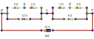
Figure 20
1
Near the top left corner of the circuit board, construct the circuit shown in Figure 20. Include the five labels a–e.
2
Add and label current arrows for the battery current (labeled I) and for each of the four parallel branches.
Label the two currents on the left I1 (top) and I2 (bottom). Similarly label the two on the right I3, and I4. Add arrows to indicate the direction of each current.
On the circuit board add three more circuits to reduce the circuit in stages described below. Include any of the circuit labels (a–e) that exist in the successive circuits. (All except (a) and (e) will eventually disappear.) Also include any previously named currents that remain.
-
aSimplify each of the two series sections into single resistors to create Circuit 20b.
-
bSimplify each of the two resulting parallel sections into single resistors to create Circuit 20c.
-
cSimplify the remaining two resistors into a single resistor to create Circuit 20d.
4
Take a Screenshot
 of the full circuit board showing all four circuits and upload it as "DC_Circuit_2.png".
5
Determine the power dissipated by the 4-Ω resistor in the left-hand circuit by adding either an ammeter or a voltmeter to the circuit. Use the reading from that meter in calculating the power, P4 Ω left.
6
Show your calculations.
7
Determine the battery current, I.
I =
A
8
Determine the voltage drop, Vce.
Vce =
V
9
What is the voltage drop across the, 4-Ω resistor in the right-hand circuit, V4 Ω right?
V4 Ω right =
V
10
Calculate the power dissipated by the 4-Ω resistor in the right-hand circuit, P4 Ω right.
P4 Ω right =
W
11
Show your calculations for 7–10.