
Thin Lenses
Introduction
The thin-lens equation is where s is the object distance (the distance of the object from the lens),s'
is the image distance (the distance of the image from the lens), and f is the focal length of the lens. The lens axis is a line perpendicular to the lens at its center. The focal plane of the lens is perpendicular to the lens axis at the focal point.
If the light is traveling in the direction from the left to the right then we have:
-
•s is positive if the object is to the left of the lens. We then say it is a real object.
-
•s is negative if the object is to the right of the lens. We then say it is a virtual object. A virtual object can only occur in optical systems containing more than one lens (or mirror).
-
•s'is positive if the image is to the right of the lens. Then it is a real image. A real image can be projected onto a screen.
-
•s'is negative if the image is to the left of the lens. Then it is a virtual image and can only be observed by looking into the lens. A virtual image cannot be projected onto a screen.
-
•f is positive when the lens is thicker at the center than at the edges. The lens is then called a positive or converging lens.
-
•f is negative when the lens is thinner at the center than at the edges. The lens is then called a negative or diverging lens.
(s' = f).
Also, rays emanating from the focal point of a thin converging lens (s = f)
will be parallel to the lens axis after refraction by the lens (s'
→ ∞). These properties are utilized in the auto-collimation method of locating the focal point of a positive lens. If an object is placed at the focal plane of the lens, the rays emerging from the lens are parallel to the lens axis. If a plane mirror is used to reflect these parallel rays back through the lens, the final image will be formed in the focal plane of the lens, a distance (f) from the lens.
Lens Combinations
When light passes through two lenses in succession, the image formed by the first lens may be thought of as the object of the second lens. Therefore, the position of the final image is calculated by successive applications of the thin-lens equation. First, the position of the image produced by the first lens(s1')
is found. The distance of this image from the second lens is then used as the object distance (s2) for the second lens and the thin-lens equation is used to calculate the final image distance (s2').
Depending on the position of the second lens relative to the first lens, the object for the second lens may be real or virtual. In this experiment we will use a virtual object (s2 negative) in finding the focal length of a diverging lens.
Objective
In this lab we will apply the thin-lens equation to the measurement of the focal length of a converging lens and of a diverging lens.Apparatus
- Optical bench
- Incandescent light source with cross arrow plate
- Viewing screen and holder
- Converging lens (marked 75 mm) and holder
- Diverging lens (marked –150 mm) and holder
- Plane mirror
Procedure
Please print the worksheet for this lab. You will need this sheet to record your data.
Positive Lens
Object Distance A
1
On the optical bench, place the screen about 35 to 40 cm from the arrow plate that is on the front of the light box. The arrow plate serves as the object. Place the converging lens between the light source and the screen. Adjust the position of the lens to form a sharply focused image of the object on the screen. Measure and record the object distance, s, (the distance between the cross arrow plate and the lens) and the image distance, s',
(the distance between the lens and the screen).
2
Use the thin-lens equation and your measured s and s'
to calculate the focal length (f) of the lens and record your result.
Object Distance B
3
Now move the screen about 10 cm farther from the light source and readjust the position of the lens to again obtain an image focused onto the screen. Measure s and s'
again and record your results.
4
Use the thin-lens equation and these new measured values of s and s'
to calculate the focal length (f) and record your result.
5
How does the average of your two focal length measurements compare with the focal length written on the plastic lens holder?
Auto-Collimation Method of Measuring f
1
Mount the positive lens on the optical bench and place a plane mirror on the side of the lens opposite the light source. Hold a white piece of paper next to the arrow plate that is on the front of the light box. (It may help to fold the paper into quarters to get a more rigid screen.) Light from the light source will pass through the lens, reflect off the mirror and then shine back through the lens to the sheet of paper. By carefully adjusting the distance between the lens and the light source, a sharp image of the object can be formed on the paper screen. It may be necessary to tilt the mirror slightly to the left or right to get the image onto the paper screen. As discussed in the Introduction, when the final image is focused onto the paper screen, the distance between the lens and the light source (object) equals the focal length of the lens.
2
Measure and record the distance between the lens and the light source that gives an image sharply focused on the paper screen. This should equal the focal length of the lens.
3
How does the focal length of the lens obtained by this auto-collimation method compare with the average of the focal lengths found by the previous method?
Measuring f for a Diverging Lens
1
Arrange the apparatus with the positive lens as in the first measurement. Separate the object from the positive lens by a distance of about two to three times the focal length of the lens. Move the screen on the optical bench in order to have the image (I1) focused sharply on the screen. Measure and record the object and image distances s1 and s1'.
2
Keep the object and positive lens fixed in position. Move the screen about 20 cm farther from the converging lens (L1), as in Figure 1, and insert the diverging lens at L2, between L1 and I1. The image at I1 is no longer formed, but the previous position of I1 is considered to act as a virtual object for the lens L2.
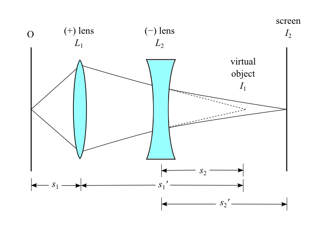
Figure 1
3
Adjust the position of the diverging lens (L2) until the image (I2) on the screen has its maximum sharpness. Measure and record the distance, s2, from L2 to I1. Record s2 as a negative number, since the location of I1 is to the right of the diverging lens and therefore it acts as a virtual object.
4
Also measure and record the distance, s2'
, from L2 to I2.
5
Use your measurements to calculate the focal length (f2) of the diverging lens. Record your result.