
Chapter 8 – Solids
Introduction
Solids are characterized by an orderly arrangement of their particles. If the order is over short distances only (local order), the solid is an amorphous solid. Charcoal and glass are amorphous solids. If the order exists throughout the entire solid (long range order), the solid is said to be a crystalline solid. Table salt and sugar are two common examples of crystalline solids. This chapter is devoted to the study of crystalline solids. Even a small crystal contains millions and millions of particles. Thus, studying the solid state could be a formidable task.8.1 Unit Cells
Introduction
However, the long range order that characterizes crystalline solids means that there is a small repeat unit, called the unit cell, that can be used to generate the entire crystal. Our study is simplified because, instead of studying the positions of the enormous number of particles that constitute the entire crystal, we need study only the small number of particles that comprise a unit cell. In this section, we define the unit cell and discuss how it is packed with atoms.Objectives
-
•Define unit cell and lattice.
8.1-1. Definition
The unit cell is the smallest repeat unit of the crystalline lattice that generates the entire lattice with translation.

Figure 8.1: Definitions of Lattice and Unit Cell
The unit cell is the smallest repeat unit of the crystalline lattice that generates the entire lattice with translation. The figure shows two different but equivalent unit cells highlighted in yellow.
8.1-2. Unit Cell Parameters
All unit cells can be uniquely characterized by their three edge lengths, (a, b, and c) and the angles (α, β, and γ) defined in Figure 8.2. They must be six-sided polygons that completely fill space; that is, no holes are present when the unit cell polygons are packed in three dimensions. As a result, there are only seven different types of unit cells. We limit our discussion to the simplest type of unit cell, the cubic unit cell. The cubic unit cell is one in whicha = b = c
and α = β = γ = 90°.
There are three types of cubic unit cells that differ only in the manner in which the particles fill the cell.
-
•simple cubic (sc)
-
•body-centered cubic (bcc)
-
•face-centered cubic (fcc)

Figure 8.2: Parameters that Define the Unit Cell Type
8.2 Cubic Unit Cells and Metallic Radii
Introduction
Unit cells must be six-sided polygons that completely fill space (no space between unit cells), and there are only seven types of unit cells that fulfill this requirement. However, our discussion is limited to only one type, the cubic unit cell.Objectives
-
•Distinguish between simple, body-centered, face-centered cubic unit cells.
-
•Determine atomic radii from the unit cell edge length or the edge length from the atomic radii.
8.2-1. The Cubic Unit Cells
There are three cubic unit cells that differ in how the particles fill the cube. In each cubic unit cell, the same atom-type occupies each of the eight corners of the cube. The unit cell type is then dictated by where else in the unit cell that atom-type is found. Note that in the images below, all spheres represent the same atom type—the color differences are used only to distinguish different positions in the cell. There are three different types of cubic unit cells.| Type of Cubic Unit Cell | Location of Identical Particles | Image |
|---|---|---|
| simple cubic (sc) | on the corners but nowhere else in the cell | 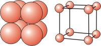 |
| body-centered cubic (bcc) | on the corners and in the center of the cell | 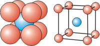 |
| face-centered cubic (fcc) | on the corners and in the centers of the six faces of the cell | 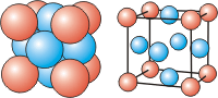 |
Table 8.1: Cubic Unit Cells
8.2-2. Metallic or Atomic Radii
Atoms are not hard spheres with distinct boundaries, so their sizes are not determined directly. However, the positions of the atoms in a solid can be determined by x-ray diffraction, and the sizes of the atoms are inferred from those distances. In this method, the radius of an atom is determined from the unit cell edge length (a), which is determined from the location of the atoms, and the assumption that the atoms touch as shown in Figures 8.3a, 8.3b, and 8.3c.
Figure 8.3a: Atom Contact in Simple Cubic Unit Cells

Figure 8.3b: Atom Contact in Face-Centered Cubic Unit Cells

Figure 8.3c: Atom Contact in Body-Centered Cubic Unit Cells
( 8.1 )
r =
| (sc) | |||||
r =
| (fcc) | |||||
r =
| (bcc) |
Relationship of Atomic Radii and Unit Cell Edge Lengths
8.2-3. Determining an Atomic Radius Exercise
Exercise 8.1:
γ-Iron adopts a fcc crystal structure with an edge length of 3.56 Å.
What is the atomic radius of iron inferred from this structure?
r =
1.26___
Use Equation 8.1: 
r =
=
= 1.26 Å
Å
| ||
| 4 |
| ||
| 4 |
8.3 Unit Cell Stoichiometry
Introduction
The number of atoms or ions in a unit cell of a compound does not have to be the same as the number of atoms in the formula of the compound, but the stoichiometry of the unit cell must be the same as the stoichiometry of the compound. Thus, a unit cell of NaCl may have many sodium and chloride ions, but the number of each ion must be the same because their stoichiometric ratio is 1:1 in the compound. However, when determining the unit cell stoichiometry, you cannot simply count all of the atoms or ions that form the unit because many of the particles may be part of more than one unit cell. In this section, we explain how to determine the stoichiometry of a unit cell.Objectives
-
•Determine the fraction of an atom that lies in a unit cell given the lattice site occupied by the atom.
-
•Determine the number of atoms, molecules, or ions in a unit cell.
8.3-1. Unit Cells Share Particles
A particle in a face contributes 1/2 particle to each unit cell, one on an edge contributes 1/4 to a unit cell, and one on a corner contributes 1/8 per cell.

Figure 8.4a: Particle Contributions to Unit Cell Stoichiometry
A particle on a face center is shared by two unit cells, so it contributes 1/2 particle to each.

Figure 8.4b: Particle Contributions to Unit Cell Stoichiometry
A particle on an edge is shared by four unit cells, so it contributes 1/4 particle to each.

Figure 8.4c: Particle Contributions to Unit Cell Stoichiometry
A particle on a corner is shared by eight unit cells, so it contributes 1/8 particle to each.
8.3-2. Contributions per Unit Cell
The particles on the eight corners combine to contribute 1 particle to a unit cell. Particles in the six face centers combine to contribute 3 particles to a unit cell. Those on twelve edges combine to contribute 3 particles per unit cell.
| 8 corners |
| unit cell |
| 1 atom |
| 8 corners |
| 1 atom |
| unit cell |
Atoms located on the corners of the unit cell contribute 1 atom per unit cell.
| 6 faces |
| unit cell |
| 1 atom |
| 2 faces |
| 3 atoms |
| unit cell |
Atoms located on the faces of the unit cell contribute 3 atoms per unit cell.
| 12 edges |
| unit cell |
| 1 atom |
| 4 edges |
| 3 atoms |
| unit cell |
Atoms located on the edges of the unit cell contribute 3 atoms per unit cell.
8.3-3. Determining the Number of Atoms in a Unit Cell Exercise
Exercise 8.2:
How many atoms are in each of the three cubic unit cells?
sc =
1_0__
Atoms lie only on the eight corners, so there is only one atom/uc.
bcc =
2_0__
Atoms lie on the eight corners and in the center of the cell, so there are
1 + 1 = 2
atoms/uc.
fcc =
4_0__
Atoms lie on the eight corners and in each of the six faces, so there are
1 + 3 = 4
atoms/uc.
8.4 Coordination Number and Geometry
Introduction
The coordination number (CN) is the number of nearest neighbors of a given particle in the crystal lattice. It determines the nature of the bonding in a crystal. The most common coordination numbers are 4, 6, 8, and 12.Objectives
-
•Define the term coordination number.
-
•Determine the coordination number of an atom or ion in a unit cell.
8.4-1. Common Coordination Numbers and their Geometries

Figure 8.5a: Coordination Number of 4

Figure 8.5b: Coordination Number of 6

Figure 8.5c: Coordination Number of 8

Figure 8.5d: Coordination Number of 12
-
•The top and bottom planes each have three particles, while the plane in the middle contains the central particle and six others forming a belt around it.
-
•The top and bottom planes each have four particles, while the plane in the middle contains the central particle and four others. The central plane is the face of a face-centered cube.
8.4-2. Coordination Number Exercise
Exercise 8.3:
The mineral rutile is an oxide of titanium that crystallizes in the tetragonal
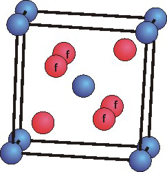 Ti atoms are blue and O atoms are red. The four O atoms marked "f" are in the cell face, but the other two are in the cell body.
(a = b > c,
α = β = γ = 90°)
unit cell. Use the unit cell shown below to determine the following for titanium oxide.
number of Ti atoms in the uc =
2_0__
Ti atoms lie on the eight corners and in the cell body, so there are
1 + 1 = 2
atoms/uc.
number of O atoms in the uc =
4_0__
Four O atoms lie in the faces and two lie in the cell body, so there are
2 + 2 = 4
atoms/uc.
Indicate any subscripted characters with an underscore (_) and any superscripted characters with a carat (^). For example, NH_4^1+ for NH41+.
simplest formula of titanium oxide =
o_TiO_2_s
The Ti:O ratio in the unit cell is 2:4 or 1:2, so the formula is TiO2.
coordination number of Ti =
6_0__
Each Ti is surrounded by six O atoms.
8.5 Density and Packing Efficiency
Introduction
It is impossible to pack spheres without introducing some void space (space that is not occupied). How well the atoms pack a unit cell depends upon the unit cell type and is given by the packing efficiency of the unit cell. Solids with tightly packed unit cells are more dense than those with low packing efficiencies. In this section, we examine the packing efficiencies of the cubic unit cells and show how to determine the density of a solid from its crystal structure.Objectives
-
•Determine relative packing efficiencies of cubic unit cells.
-
•Determine the density of a solid from its crystal structure.
8.5-1. Density
Density is the mass-to-volume ratio of a substance. Densities of metals range from 0.53 g/cm3 for lithium to 22.65 g/cm3 for iridium.8.5-2. Packing Efficiency
Packing efficiency is the fraction of the unit cell that is occupied by particles. Closest packed spheres pack with a packing efficiency of 74%.
-
•a = the length of a side of the unit cell, so a3 is the volume of the unit cell.
-
•r = the radius of the atoms that occupy the unit cell, so (4/3)πr3 is the volume of a single atom in the unit cell.
-
•N = the number of atoms in the unit cell, so N(4/3)πr3 is the volume occupied by all of the atoms in the unit cell.
8.5-3. Packing in Simple Cubes

Figure 8.6
(a = 2r).
The properties of the simple cubic unit cell:
-
•r = 0.5a
-
•N = 1 atom/unit cell
-
•packing efficiency = 52%
-
•coordination number = 6
8.5-4. Packing in Face-Centered Cubes

Figure 8.7
(fd = 4r)
and is related to the unit cell edge length (a) by the Pythagorean theorem.
The properties of the face-centered cubic unit cell:
-
•r =
a = 0.354a
2 4 -
•N = 4 atoms/unit cell
-
•packing efficiency = 74%
-
•coordination number = 12
8.5-5. Packing in Body-Centered Cubes

Figure 8.8
bd = 4r.
The body diagonal is related to the face diagonal (fd) and the cell edge (a) by the Pythagorean theorem. The relationship between the cell edge and the face diagonal was derived in the discussion of the fcc unit cell.
The properties of the body-centered cubic unit cell:
-
•r =
a = 0.433 a3 4 -
•N = 2 atoms/unit cell
-
•packing efficiency = 68%
-
•coordination number = 8
8.5-6. Packing Efficiency and Coordination Number
As shown in the previous sections, the packing efficiency of a unit cell depends only on the cell type; it is independent of edge length and atomic radius because both cancel in the calculation. Table 8.2 gives the packing efficiencies of the cubic unit cells and coordination numbers of the atoms in them. As might be expected, the packing efficiency increases as the number of atoms in the unit cell and the number of atoms that are packed around each atom (coordination number) increases.|
Lattice Type |
Packing Efficiency |
Coordination Number |
|---|---|---|
| Simple | 52% | 6 |
| Body-centered | 68% | 8 |
| Face-centered | 74% | 12 |
Table 8.2: Packing Efficiencies and Coordination Numbers of Cubic Lattices
8.5-7. Packing Efficiency and Crystal Properties
Table 8.3 shows the unit cell types, metallic radii, and densities of selected metals that adopt cubic unit cells. Almost half of the volume of a sc unit cell is void space, so the sc unit cell is not a favorable way to pack and metals do not generally crystallize in sc lattices. Indeed, the only known example of a metal adopting the sc unit cell is a form of polonium. The densities of the Group 1A elements are all quite low because their atoms are not very dense (they have the greatest volume and smallest mass of any atom in their period) and because they pack in the less efficient bcc lattice. The impact of packing efficiency on the density can be seen by comparing K and Ca, which are next to one another in the periodic chart and have nearly identical metallic radii. Ca is almost 60% more dense because it crystallizes in the more efficient fcc unit cell. The effect can also be seen by comparing two forms of iron. Iron normally crystallizes with a bcc structure known as α-iron, but it also can be made to adopt a more efficiently packed fcc structure called γ-iron by adding small amounts of carbon and manganese or nickel and chromium. The tighter packing of γ-iron makes it so corrosion-resistant that it is known as stainless steel.| Metal |
Unit Cell |
Radius (Å) |
Density (g/cm3) |
|---|---|---|---|
| Ag | fcc | 1.44 | 10.5 |
| Al | fcc | 1.43 | 2.70 |
| Au | fcc | 1.46 | 19.3 |
| Ba | bcc | 2.48 | 3.59 |
| Ca | fcc | 2.35 | 1.55 |
| Cu | fcc | 1.28 | 8.96 |
| K | bcc | 2.35 | 0.86 |
| Li | bcc | 1.55 | 0.53 |
| Na | bcc | 2.35 | 0.97 |
| Ni | fcc | 1.25 | 8.90 |
| Pb | fcc | 1.75 | 11.35 |
| Pt | fcc | 1.39 | 21.45 |
| Rb | bcc | 2.48 | 1.53 |
| Sr | fcc | 2.15 | 2.6 |
Table 8.3: Unit Cell Type, Metallic Radii, and Densities of Selected Metals with Cubic Unit Cells
8.5-8. Exercise on Determining Packing Efficiency
Exercise 8.4:
Rhodium (Rh, Mm = 102.9 g/mol) crystallizes in a face-centered cubic unit cell that is 3.79 Å on a side. Determine the atomic radius, packing efficiency, and density of the unit cell based on these data. See Section 8.5-4. for help with fcc unit cell packing. Express your answers with three digits.
The atomic radius of Rh is r =
1.34__3_
For a face-centered cubic unit cell
r = 0.354a = 0.354(3.79) = 1.34 Å.
Å
The volume of one Rh atom is V =
10.08__3_
The volume of a sphere is
V = (4/3)πr3 = (4/3)π(1.34 Å)3 = 10.08 Å3 Å3
V = (4/3)πr3 = (4/3)π(1.34 Å)3 = 10.08 Å3 Å3
The number of Rh atoms present in one unit cell is n =
4_0__
A face-centered cubic unit cell has 4 atoms per unit cell (1 from the corners and 3 from the face centers).
The volume of all of the atoms in the unit cell is V =
40.3__3_
The volume of all atoms is (4 atoms/uc)(10.08 Å3/atom) = 40.3 Å3.
Å3
The volume of the unit cell is V =
54.4__3_
The volume of a cube is Vcell = a3 = 3.793 = 54.4 Å3.
Å3
The packing efficiency of the cell based on these numbers is PE =
74.0__3_
PE =
=
= 0.740 or 74.0%
%
| volume of atoms in uc |
| volume of uc |
| 40.3 Å3 |
| 54.4 Å3 |
The mass of all atoms in the unit cell is m =
6.8372e-22__3_
Four atoms per unit cell and mass of one atom is molar mass divided by Avogadro's number:
m = 4 Rh atoms/uc ×
×
= 6.842e−22 g Rh
g
| 102.9 g Rh |
| 1 mol Rh atoms |
| 1 mol Rh atoms |
| 6.02e23 Rh atoms |
The volume of the unit cell in cm3 is V =
5.44399e-23__3_
54.4 Å3 =
= 5.44e−23 cm3
cm3
| 1 cm3 |
| (108)3 Å3 |
The density of Rh derived from these data is d =
12.6__3_
d =
=
= 12.6 g Rh/cm3
g/cm3
| mass of atoms |
| volume of unit cel |
| 6.842e−22 g Rh |
| 5.44e−23 cm3 |
8.6 Band Theory of Simple Metals
Introduction
The metallic bond is the interaction that holds metal atoms in the solid. The strength of the metallic bond varies considerably depending upon the metal. Consequently, metals vary from very high-melting substances such as iron (mp = 1535 °C) to low-melting substances such as mercury (mp = –39 °C). Metals have low ionization energies and readily lose their valence electrons to become positively charged ions. In a metallic bond, valence electrons from all of the metal atoms in the solid are delocalized over the entire metal. The metal cations are immersed in the sea of valence electrons, and the electrostatic force exerted between the cations and the surrounding electrons holds the positively charged metal ions in place. Bonding and electrical conduction in metals is best understood in terms of band theory, which is the extension of molecular orbital theory (Section 6.5) to the very large number of atoms found in a metal.Objectives
-
•Describe a metallic bond.
-
•Explain what is meant by an energy band.
-
•Define the Fermi level and identify it in a band diagram.
-
•Explain how a metal can be a conductor even when all of its valence orbitals are full.
-
•Define the band gap.
-
•Distinguish between a valence band and a conduction band.
-
•Distinguish between a metallic conductor, a semiconductor, and an insulator based on their band structures.
8.6-1. Introduction to Band Theory
The molecular orbital description of the delocalized electrons in metallic bonds provides a more complete picture of metallic bonding as well as an explanation for the electrical conductivity of metals. The explanation, which is called band theory, applies the concepts presented in the molecular orbital discussion in Chapter 6 to a very large number of orbitals. The orbitals in the solid are constructed in the same way as those in a molecule, but they apply to a crystal rather than a molecule, so they are called crystal orbitals rather than molecular orbitals. As the number of orbitals increases, the adjacent orbitals become more similar, and the resulting energy levels get closer together. In a piece of metal, the number of atoms and atomic orbitals in each crystal orbital is enormous (on the order of Avogadro's number), so the energy levels are so close that they can no longer be distinguished and the system is described in terms of energy bands rather than energy levels. The formation and properties of bands is the topic of this section.8.6-2. Properties of Multi-Orbital Systems
Increasing the number of orbitals in a molecular orbital increases the energy spread of the molecular orbitals while decreasing the energy separation between adjacent orbitals.

Figure 8.9: Energy Levels in Two- and Ten-Orbital Systems
Only the two orbitals at lowest energy and the one at highest energy of the ten-orbital system are shown.
8.6-3. The Definition of a Band
The energy levels in a metal are so close that they are represented by a band of energy.

Figure 8.10: Band Formation
The dotted lines represent the energy spread and show that the top and bottom energies begin to level off as the number of orbitals gets large.
8.6-4. Fermi Level
The highest-energy occupied level in a metal is called the Fermi level.

Figure 8.11: Band Structure for a Metallic Conductor
Note: the shaded portion of the rectangle indicates the portion of the band that contains filled orbitals.
8.6-5. Valence Band, Conduction Band, and the Band Gap
The band gap is the energy separation between the valence and conduction bands.

Figure 8.12: The Band Gap
8.6-6. Conductivity
Conductors have no band gap, semiconductors have moderate band gaps, and insulators have large band gaps.

Figure 8.13

Figure 8.14

Figure 8.15
8.6-7. Band Overlap
A metal with filled orbitals can be a conductor if the bottom of a band formed from empty orbitals overlaps the top of the band formed from filled orbitals.

Figure 8.16: A Metallic Conductor Produced from Overlapping Bands
8.7 Ionic Solids and Ionic Radii
Introduction
The ionic bond (Chapter 4) is the interaction that holds the ions of an ionic substance in the solid state. In order to melt or break an ionic crystal, ionic bonds must be broken, and ionic bonds are usually quite strong. Consequently, ionic substances are typically hard and have high melting points, which means that they are typically solids at room conditions. However, the strength of an ionic bond depends upon the charge of the ions and their separation (Coulomb's Law). Thus, ionic compounds with small ions (small separation) that are highly charged have higher melting points than ionic compounds with large ions that carry lower charges. For example, the melting point of MgO (small ions with +2 and –2 charges) is 2852 °C, while that of CsI (large ions with +1 and –1 charges) is 626 °C. In this section, we examine the structure of some simple ionic compounds.Objectives
-
•Describe the sodium chloride structure.
-
•Distinguish between the NaCl and CsCl structures.
-
•Determine the radius of an ion given the ionic radius of the other ion and the distance between the ions in a compound.
8.7-1. Ionic Radii
The distance between two adjacent ions in a crystal is equal to the sum of their ionic radii. For example, the distance between Li1+ and I1– ions in a crystal of LiI is 2.96 Å, so we can writerLi + rI = 2.96 Å.
Ionic radii have been determined by examining many such distances. The ionic radii of the alkali metal ions (Group 1A) and the halide ions (Group 7A) are given in Table 8.4.
| Cation |
Radius (Å) |
Anion |
Radius (Å) |
|
|---|---|---|---|---|
| Li1+ | 0.90 | F1– | 1.19 | |
| Na1+ | 1.16 | Cl1– | 1.67 | |
| K1+ | 1.52 | Br1– | 1.82 | |
| Rb1+ | 1.66 | I1– | 2.06 | |
| Cs1+ | 1.81 |
Table 8.4: Ionic Radii of Group 1A and 7A Ions
8.7-2. Ionic Radii Exercise
Exercise 8.5:
What is the ionic radius of Mg2+, if the Mg–Cl distance in MgCl2 is 2.53 Å?
the ionic radius of Cl1– from Table 8.4 =
1.67_0__
The chloride ionic radius given in Table 8.4 is 1.67 Å.
Å
rMg =
0.86_0__
The Mg–Cl distance is the sum of the ionic radii: rMg + rCl = 2.53 Å.
Solve for the magnesium ionic radius:
rMg = 2.53 − rCl = 2.53 − 1.67 = 0.86 Å.
Å
8.7-3. LiI
Not all of the particles in an ionic solid are identical, but the same structural descriptions that are applied to metallic solids can be used to understand the crystal structure of many ionic compounds. For example, most of the alkali halides have a preference for a structure in which the anions pack in a face-centered cubic unit cell, as shown in Figure 8.17a, with the cations filling the void space as in Figure 8.17b.
Figure 8.17
(rcation = 0.414 ranion).
LiI nearly adopts the ideal structure (rLi/rI = 0.44) and has a very high packing efficiency. However, the Li1+ ions are slightly too large to fit into the holes, so the I1– ions are pushed apart slightly, so they no longer make contact.
8.7-4. LiCl

Figure 8.18: LiCl Unit Cell
8.7-5. Packing Exercise
Exercise 8.6:
Use ionic radii (rLi = 0.90 Å; rCl = 1.67 Å) and the figure to determine the void space (highlighted in red) between chloride ions in LiCl.
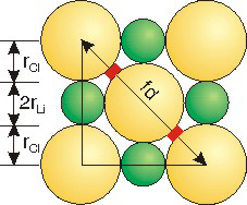
the unit cell edge is a =
5.14___
a = 2rLi + 2rCl = 2(0.90) + 2(1.67) = 5.14
Å
the face diagonal is fd =
7.269___
Å
| fd2 | = | a2 + a2 = 2(5.14)2 |
| fd | = | 7.27 |
four chloride ionic radii =
6.68___
4(1.67) = 6.68
Å
the void space =
0.294_0.06__
The void space is one-half of the difference between the face diagonal and the four chloride radii:
r = (7.27 − 6.68)/2 = 0.3.
Å
8.7-6. NaCl
Sodium chloride adopts the same structure type as lithium chloride. In fact, this structure type is called the sodium chloride structure, and LiCl is said to crystallize in the sodium chloride structure. In sodium chloride, the sodium cation is considerably larger than the ideal hole created by closest packed chloride anions. As shown in Figure 8.19, the chloride anions are moved even farther apart to accommodate the larger sodium ions. While this expansion of the packing in the unit cell lowers the packing efficiency, there is little energetic cost because each ion is still in direct contact with six ions of opposite charge. The major change in this expanded structure is that the like charges (anion-anion and cation-cation) are further separated, which is energetically favorable.
Figure 8.19: NaCl Structure
8.7-7. CsCl

Figure 8.20a: CsCl Unit Cell
CsCl in NaCl structure

Figure 8.20b: CsCl Unit Cell
The CsCl structure
8.8 Network Covalent Solids
Introduction
Covalent solids are like ionic solids in that they are very large networks of particles rather than discrete molecules. They differ from ionic solids in that the particles are atoms, not ions, and they are held in their lattice sites by covalent bonds rather than ionic bonds. Because the atoms in the lattice are attached by strong covalent bonds, the materials have very high melting points and are very hard. In this section, we examine the structures of several common network covalent solids.Objectives
-
•Describe the structure of graphite and explain why graphite is a lubricant.
-
•Describe the structures of diamond and the semiconductors Si and Ge.
-
•Describe the similarity between the structure of diamond and the semiconductors ZnS, GaAs, and IP.
8.8-1. Graphite
The carbon atoms in graphite are sp2 hybridized and covalently bound together into a two-dimensional array in which the C–C distances are 1.4 Å (see Figure 8.21a). Layers of the two-dimensional arrays are held together loosely (3.4 Å between layers as shown in Figure 8.21b) by intermolecular interactions. The covalent bonding within the layer gives graphite a high melting temperature. The large number of covalent bonds also produces band structures that make it a good conductor. However, the interaction between the layers is weak, so the layers can slip over each other, which makes graphite an excellent lubricant.
Figure 8.21: Graphite
Ball-and-stick and space filling models of graphite that show a small portion of three layers.
8.8-2. Buckyball
Fullerenes are carbon compounds with structures based on the graphite structure. The most common fullerene is C60, which is called buckminster-fullerene (or buckyball) after the architect of the geodesic dome. Buckyball was discovered in the early 1980's. It contains 20 hexagons and 12 pentagons and is the shape of a soccer ball. The hexagons are the same units that form the basis of graphite, but the pentagons are required for closure. A great deal of research was done on fullerenes to develop new technologies. For example, efforts were made to use it as a molecular ball-bearing lubricant, and to encapsulate drugs in its cavity, so they could be released slowly in the body. Buckyball is also a superconductor, so efforts were made to take advantage of this property as well. However, no practical uses of buckyball have yet been developed.
Figure 8.22: Buckyball
Figure (a) shows the stick model of Buckyball that includes only the bonds to emphasize the hexagons and pentagons. Figure (b) is the ball-and-stick model that includes the carbon atoms.
8.8-3. Nanotubes
Nanotubes are based on the graphite structure. They are basic building blocks in molecular electronics.

Figure 8.23: Nanotube
The tube is viewed down its axis in a and along its side in b.
8.8-4. Diamond
Its strong bonds and structure make diamond the strongest substance known.

Figure 8.24: Diamond Structure
8.8-5. Zinc Blende
The zinc blende structure is common amongst semiconductors.

Figure 8.25: Zinc Blende Structure
8.8-6. Silica
Silica, silicon dioxide, is encountered most commonly as sand, which is used to make glass, cement, and ceramics. The crystalline form of silica that is found at room conditions is known as quartz. Quartz is based on a three-dimensional covalent network of SiO4 tetrahedra. A high temperature form of SiO2 (known as high cristobalite) is shown in the Figure 8.26. The silicon atoms (the gray spheres) also adopt the diamond-type structure but, in this structure, there is an oxygen atom (red sphere) located between each pair of silicon atoms.
Figure 8.26: Structure of High Cristobalite, a Form of Quartz
8.8-7. Zeolite Structure
Zeolites are characterized by molecular scale channels.
(1 angstrom = 10 nm).
The aluminosilicate framework is anionic, so natural zeolites are commonly found as their sodium salts. The cations sit inside the cavities. Small molecules can also get into the channels and interact with the oxygen atoms in the aluminosilicate framework, which leads to many uses for zeolites.

Figure 8.27: Zeolite
(a) A section of a zeolite showing a series of channels. Al or Si atoms sit at the end of each line with O atoms bridging them. The openings in the structure that are too small for other molecules to enter are shown as closed surfaces. (b) The pore of this zeolite is formed by a ring that contains 12 atoms (Si and Al) and is 7 Å in diameter. A benzene molecule, which is about 4 Å across, is shown for comparison.
8.8-8. Zeolite Function
Molecular sieves-
•The interaction between small molecules in the cavities and the oxygen atoms in the framework keeps the small molecules from leaving, so zeolites are used as molecular sieves. One common use is as a drying agent because water is small and interacts very strongly with the walls via hydrogen bonding. Consequently, when zeolite is added to a wet liquid, the water molecules enter the cavities but do not exit. The molecular sieves are then filtered out of the liquid to leave a dry liquid behind. The sieves can be restored by placing them in a hot oven where the thermal energy is sufficient for the water molecules to break their interactions with the framework.
-
•The sodium ions are only loosely bound in the cavities, so they are easily displaced by other ions. Thus, zeolites can also be used for ion-exchange. Perhaps the most common ion-exchanger is the water softener. Water hardness is due to Ca2+ and Mg2+. When "hard water" is passed through a zeolite column, the Ca2+ and Mg2+ displace Na1+ because the more highly charged ions interact more strongly. Thus, the water that leaves the column contains Na1+ rather than Ca2+ and Mg2+, so it is "soft water."
-
•Chemistry can take place inside the pores. Indeed, some reactions that occur with difficulty on their own occur with relative ease within the cavities of a zeolite. The enhanced reactivity results because interactions with the aluminosilicate framework can make substances more reactive, i.e., zeolites can function as catalysts. The pore size dictates the size of both the reactants and the products, so chemists can select to react only certain molecules in a mixture by selecting a zeolite with the appropriate pore size to exclude larger molecules. Chemists also create zeolites with chemical groups attached to them that enhance certain reactions; i.e., they functionalize zeolites.
-
•Confinement and transportation of large amounts of gases presently requires a combination of very large volumes, very high pressures, and/or very low temperatures. However, storing the gases in the cavities of zeolites is presently being pursued by chemists and engineers. The process would involve synthesizing a zeolite with the cavity size appropriate for the gas and mixing the gas with the zeolite to get the gas molecules into the pores. Once the zeolite is saturated with the gas, the conditions (temperature, pressure, cation, or other method) would be changed to cause a structural change in the zeolite that would trap the gas. Restoring the original conditions would restore the original zeolite structure, so the gas would be released.
8.8-9. Clays
Clays are the most abundant minerals found in soils, rocks, and waters. Like zeolites, they are usually aluminosilicates. However, Mg is substituted for Al in many clays, and Fe fills certain of the Al sites in some clays to give them a red color. All clays exhibit a two-dimensional layered lattice structure rather than the porous network structure of zeolites. As shown in the following figures, the two major types of clays, kaolinite and smectite clays, differ in the organization of tetrahedral (SiO4) and octahedral (AlO6 or MgO6) building blocks. The differences in their structure in turn result in dramatically different properties for these two types of clays.
Figure 8.28a: Kaolinite Clay

Figure 8.28b: Smectite Clay
8.9 Molecular Solids and Atomic Radii
Introduction
Molecular compounds form molecular solids. The molecules are held in the condensed states by relatively weak intermolecular forces (Table 7.2: Relative Strengths of Interaction). Because these forces are usually much weaker than those responsible for ionic or covalent solids, molecular solids tend to have lower melting points and are usually softer than the other solids. However, their properties can be quite diverse, as evidenced by the fact that hydrogen, water, table sugar (C12H22O11), dry ice, and iodine form molecular solids that have melting points that range from –259 °C for H2 to 186 °C for sugar, a range of over 400 °C. In addition, the intermolecular forces are typically tens of kilojoules, while covalent bond strengths are hundreds of kilojoules. Thus, covalent bonds are not broken when a substance melts, so molecules retain their identity in the liquid state.8.9-1. Van der Waals Distance and Bond Length
Atoms that are closer than the sum of their van der Waals radii are interacting.

Figure 8.29: Four Molecules in Crystalline X2
8.9-2. Representing Molecules with van der Waals Radii
The radii of the atomic spheres used in space-filling models are proportional to their van der Waals radii. The definition of the van der Waals radius is clarified in Figure 8.30, which is identical to Figure 8.29 except that space-filling representations are used rather than ball-and-stick. Note that the atomic spheres of X penetrate one another in an X2 molecule, which means that the two atoms are much closer than the sum of their van der Waals radii. Two atoms much closer than the sum of their van der Waals radii are interacting strongly, so there is a bond between the two X atoms. The spheres on adjacent molecules are touching but not penetrating, so the X atoms of different X2 molecules interact, but only weakly.
Figure 8.30: van der Waals Radii
8.9-3. Comparing Molecular Representations

Figure 8.31a: Molecular Representations
In the ball-and-stick representation, spheres are used to indicate the positions but not the
sizes of the atoms.

Figure 8.31b: Molecular Representations
When atomic size is represented by the covalent radii, bonds are shown as the contact of spheres

Figure 8.31c: Molecular Representations
When atomic size is given with van der Waals radii (space-filling), bonds are indicated by the
penetration of spheres.
8.9-4. Table of Radii
|
|||||||||||||||
|
|||||||||||||||
|
|||||||||||||||
|
Table 8.5: Covalent and
van der Waals Radii in Å
(1 Å = 100 pm)
of Selected Nonmetals
van der Waals Radii in Å
(1 Å = 100 pm)
of Selected Nonmetals
8.9-5. Radii Exercise
Exercise 8.7:
What is the van der Waals distance in graphite as shown in Figure 8.21?
dvdw =
3.4_0__
The carbon atoms in adjacent layers are touching but not penetrating, so the van der Waals distance is the distance between layers, which is 3.4 Å.
Å
What is the van der Waals radius of carbon as determined from this distance?
rvdw =
1.7_0__
The van der Waals radius is one-half of the van der Waals distance,
so the van der Waals radius of a carbon atom is 1.7 Å, in agreement with its entry in Table 8.5.
Å
8.9-6. Bond Length Exercise
Exercise 8.8:
r =
2.21___
The bond length is the sum of the covalent radii of the bound atoms.
L(Ge–Cl) = rcov(Ge) + rcov(Cl) = 1.22 + 0.99 = 2.21 Å Å
L(Ge–Cl) = rcov(Ge) + rcov(Cl) = 1.22 + 0.99 = 2.21 Å Å
8.10 Comparison of Solid Types
Introduction
Objectives
-
•Determine the relative melting points of two substances based on the type of solid they form.
8.10-1. Comparison of Solid Types
| Type of Solid | Particles | Force of Interaction | Strength of Interaction* | Examples |
|---|---|---|---|---|
| Metallic | Atoms | Metallic Bonds | Variable | Na, Cu, Ag |
| Ionic | Ions | Ionic Bonds | Strong | NaCl, NH4Br |
| Covalent | Atoms | Covalent Bonds | Strong | ZnS, C, SiO2 |
| Molecular | Molecules | Intermolecular | Weak to Moderate | CO, H2O, CCl4 |
| * The strength of interaction dictates the melting and boiling points and the hardness of the substance. | ||||
Table 8.6: Comparison of Solid Types
8.10-2. Questions
Exercise 8.9:
Choose the substance in each pair that has the higher melting point.
-
NaF The higher melting substance is the one with the stronger forces. Both of these substances are ionic, so ionic bonds must be broken to melt either substance. The relative force of attraction can be obtained by using Coulomb's Law. The substance with the greater q1q2 product is expected to have the stronger force of attraction and the higher melting point. Therefore, MgO is the higher melting material because the force of attraction between Mg2+ and O2– ions is much greater than between Na1+ and F1– ions. The melting points are: MgO = 2852 °C; NaF = 993 °C.
-
MgO
-
NaCl
-
Cl2 NaCl is an ionic substance, so ionic bonds must be broken to melt it. Cl2 is a molecular substance, so much weaker intermolecular forces must be broken. Thus, NaCl is the higher melting substance. An indication of how much stronger the forces in NaCl are is seen in the fact that NaCl is a solid at room conditions, while Cl2 is a gas.
-
SiO2
-
SO2 Recall that SiO2 is a network covalent material, so it is expected to have a very high melting point. SO2 is a molecular substance, so it is expected to have a much lower melting point. Thus, SiO2 is the higher melting substance. SiO2 (quartz) is a solid at room conditions, while SO2 is a gas.