
Chapter 14 – Inorganic Chemistry
Introduction
Organic chemistry is based on the chemistry of carbon, so that leaves the chemistry of over 100 other elements to be characterized as inorganic chemistry. The chemistry of many of these elements is very rich. In this final chapter, we focus on only one segment of these elements, the transition elements, and introduce only some of their fascinating chemistry.14.1 Ligands and Coordination
Introduction
The molecules and ions that are bound to metals are called ligands. The ligands are said to coordinate to the metal, and the compounds are called coordination compounds.Prerequisites
-
•5.6 Determining Lewis Structures
-
•6.1 Molecular Shapes
-
•12.1 Lewis Acids and Bases
-
•2.1 The Nature of Light
Objectives
-
•Describe the common coordination geometries adopted by transition metals.
-
•Explain what a ligand is and give some examples.
14.1-1. Coordination
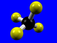
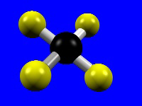
The number of donor atoms bound to the metal is called the coordination number of the metal, and the spatial arrangement of the ligands is called the metal's coordination geometry. The most common coordination numbers are 4, 5, and 6, and their common coordination geometries are described below. Octahedral coordination (coordination number = 6) is the most common coordination geometry in this chapter.| Coordination Number = 4 | Tetrahedral | Square Planar |
|---|---|---|
 |
 |
|
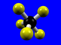
| Coordination Number = 5 | Trigonal Bipyramidal | Square Pyramidal |
 |
 |
|
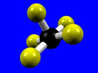
| Coordination Number = 6 | Octahedral | |
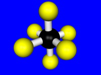 |
Table 14.1: Common Coordination Numbers
14.1-2. Ligands
Transition metals are frequently found in complexes, substances in which the metal is bound to several molecules and/or ions. The molecules or ions that bind to a metal are called ligands. Ligands have lone pairs and function as Lewis bases, while metal ions have empty orbitals that can be used to share the lone pair; i.e., metals are Lewis acids. Although most ligands use only one lone pair to bond to a metal, some ligands can use more than one. If such ligands bond to two different metals, they are called bridging ligands, because they form a bridge between the two metals. If more than one lone pair from a ligand binds to the same metal, the ligand is said to be a chelating ligand.
Figure 14.1a: Some Common Ligands
Ligands contain lone pairs that are used to bond to the metal. Ligands can be molecules (top row) or
ions (bottom row).

Figure 14.1b: Some Common Bridging Ligands
Ligands that contain two lone pairs that can bond to two different metals are called bridging ligands because they can bridge two metals. Ligands (a) (cyanide ion) and (b) bridge with 180° bond angles, while ligand (c) (chloride ion) can bridge with ~109° bond angles. Note that these ligands can bridge, but they do not have to. For example, chloride forms bridges in only a small fraction of its compounds with transition elements.

Figure 14.1c: Some Common Chelating Ligands
14.2 Ligand Fields
Introduction
The chemistry of the transition metals can be understood in terms of the interaction between the ligands and the metal's d-orbitals. The ligands generate an electric field around the metal that alters the energy of the orbitals and strongly influences the properties of the metal.Prerequisites
Objectives
-
•Explain how the d-orbital energies are affected by their orientation to the ligands.
-
•Determine the total spin from the number of unpaired electrons.
14.2-1. d-orbitals
The five d-orbitals have the following electron distributions:| Name | Shape | Electron Distribution |
|---|---|---|
| z2 |  |
along the z-axis and in a donut-shaped cloud in the xy plane |
| x2–y2 | 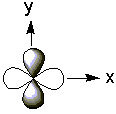 |
along the x and y axes |
| xy | 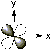 |
in the xy plane but directed between the axes |
| xz | 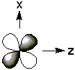 |
in the xz plane but directed between the axes |
| yz | 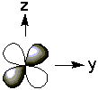 |
in the yz plane but directed between the axes |
Table 14.2: Electron Distributions in the d-Orbitals
14.2-2. The Coordinate System
As shown in Figure 14.2, the metal-ligand bonds in an octahedral coordination form the coordinate system for the d-orbitals. Thus, the z2 and x2-y2 orbitals are directed along the axis of the metal-ligand bonds as they are directed along the z and the x and y axes, respectively.
Figure 14.2: Coordinate System in Octahedral Coordination
14.2-3. d-Orbital Energies in Octahedral Fields
The energies of the d-orbitals change in the electric field produced by the ligands. The electric field is called a ligand field.

Figure 14.3: d-Orbital Energies in an Octahedral Ligand Field
The energy separation between the two groups of d-orbitals in an octahedral field is given the symbol Δ. A strong field ligand produces a large Δ, while a weak field ligand produces a small one.
14.2-4. Color Complement
The color perceived for a substance is the complement of the one that is absorbed.
| Observed Color | Absorbed Color |
|---|---|
| green | red |
| blue | orange |
| violet | yellow |
| red | green |
| orange | blue |
| yellow | violet |
Table 14.3: Complementary Colors

Figure 14.4: Color Wheel
14.2-5. Color and Energy
Recall from Section 2.2 that the energy of a photon (bundle of light energy) is proportional to its frequency: where h is Planck's constant (6.63 × 10⁻³⁴ J/s) and ν is the frequency of the photon in s–1. Thus, the energy of visible photons increases in the order red < orange < yellow < green < blue < violet. Substances that are colored absorb photons in the visible region of the electromagnetic spectrum to promote an electron from one orbital to another that is higher in energy. The energy difference between the two orbitals (ΔE) can be determined from the frequency of the light that is absorbed by the following relationship:
Figure 14.5: Energy and Color
The double arrows connect complementary colors. Thus, if a substance appears the color at one end of the double arrow, then it absorbs light at the other end of the arrow.
14.2-6. Color in Transition Metal Ions
Many transition metal ions are colored because the energy separation between the d-orbitals lies in the visible region. The light that is absorbed in these transitions must obey the following relationship: where Δ is the energy separation between the d-orbitals and ν is the frequency of the absorbed light. Thus, the relative field strengths of ligands can sometimes be determined from the color of the compounds they form with a metal.
Exercise 14.1:

Use the color wheel and relative energy figures and the fact that CoBr2 is green while CoCl2 is blue to determine the relative field strengths of the bromide and chloride ions.
-
CoBr2 is green. What color does it absorb?
-
violet Violet is not the complement of green.
-
blue Blue is not the complement of green.
-
green The color that is absorbed is the complement of the one that is observed.
-
yellow Yellow is not the complement of green.
-
orange Orange is not the complement of green.
-
red Red is the complement of green, so a green compound absorbs red light.
-
CoCl2 is blue. What color does it absorb?
-
violet Violet is not the complement of blue.
-
blue The color that is absorbed is the complement of the one that is observed.
-
green Green is not the complement of blue.
-
yellow Yellow is not the complement of blue.
-
orange Orange is the complement of blue, so a blue compound absorbs orange light.
-
red Red is not the complement of blue.
-
Which is the stronger field ligand?
-
chloride Orange light has more energy than red, so the energy separation in a compound that absorbs orange light is greater than one that absorbs red light.
-
bromide Orange light has more energy than red, so the energy separation in a compound that absorbs orange light is greater than one that absorbs red light.
14.2-7. Electron Spin
We now consider the effect of Δ on the spin of transition metal ions. The spin on an ion is the sum of the individual electron spins. Recall from Section 2.5 that the spin quantum number for an electron is either +1/2 or –1/2. The spin of two paired electrons is+1/2 + (−1/2) = 0.
Therefore, only unpaired electrons contribute to the spin on a metal ion. In Chapter 2, we used Hund's Rule to determine the number of unpaired electrons in a d sublevel. Hund's Rule is based upon the fact that energy is required to pair two electrons in an orbital. This energy is called the pairing energy (PE).
In the presence of an octahedral ligand field, the d-orbitals are in two groups separated by an energy Δ, so there are two ways in which four to seven electrons can occupy the five orbitals. Which way they actually fill the d-orbitals depends upon the relative sizes of Δ and the pairing energy. Remember that the electrons fill in such a way to minimize their energy.
-
•high spin: If Δ < PE, the electrons enter the higher energy set of orbitals before pairing. This is most likely in the presence of weak field ligands.
-
•low spin: If Δ > PE, the electrons pair before entering the higher energy set. This is most common when strong field ligands are present.

Figure 14.6a: Spin and Field Strength: No Field

Figure 14.6b: Spin and Field Strength: Weak Field

Figure 14.6c: Spin and Field Strength: Strong Field
14.3 Isomers
Introduction
Inorganic compounds can form geometrical isomers when the ligands can situate in different ways relative to one another. In this section, we consider the possible isomers of ML2X4 and ML3X3 in an octahedral coordination geometry.Objectives
-
•Identify cis and trans isomers of ML2X4 and meridial and facial isomers of ML3X3.
14.3-1. Isomers
Two ligands in an octahedral geometry can be cis or trans, while three ligands can be meridial or facial.

Figure 14.7: Cis and Trans Isomers
Two cis ligands (red spheres) are adjacent to one another, while two trans ligands are opposite one another.

Figure 14.8: Ligand Placement in Facial and Meridial Isomers
Three ligands in a meridial isomer lie on a meridian of the octahedron, while three ligands in a facial isomer share a face of the octahedron.
14.4 Metals in Biology
Introduction
Plants extract energy from the sun to synthesize carbohydrates (Cn(H2O)n) in a process called photosynthesis, and animals extract the energy from the carbohydrates in a process called respiration. Metals are key to both processes.14.4-1. Photosynthesis
Photosynthesis involves a four-electron transfer reaction that is catalyzed by metals.

Figure 14.9: Chorophyll
14.4-2. Heme
Oxygen transport is carried out by binding O2 to iron in a heme group.
 oxyheme
Figure 14.10: Action of Heme
14.4-3. Hemoglobin
Hemoglobin is comprised of 600 amino acids and consists of four similar units (Figure 14.11a). Each unit contains an active site. Although each active site (Figure 14.11b) is the center of the oxygen transport process, the polypeptide chains play critical roles in stabilizing the binding and release of four oxygen molecules.
Figure 14.11: Hemoglobin

Figure 14.12: Amino Acids Involved in Sickle-Cell Anemia
14.4-4. Cisplatin — Drug Action
Cisplatin binds to DNA, which causes a shape modification in the DNA that hinders its function.

Figure 14.13: Replacement of Chloride with Water

Figure 14.14: Cisplatin Bound to Two Sites of a DNA Strand

Figure 14.15: Changes in DNA Double Helix Due to Cisplatin Binding
14.5 Metals as Catalysts
Introduction
The interaction between a ligand and a metal can be used to provide new pathways for chemical reactions; i.e., metals catalyze some reactions. A catalyst is classified as either homogeneous (the catalyst is in the same phase as the reactants) or heterogeneous (the catalyst is in a different phase than the reactants).Prerequisites
14.5-1. Heterogeneous Catalysts
Heterogeneous catalysts are solids that catalyze solution or gas phase reactions on their surfaces.
-
1H2 adsorbs on the surface as H atoms.
-
2H atoms migrate across the surface.
-
3An ethylene molecule adsorbs on the surface by using its pi electrons.
-
4H atoms and ethylene molecules migrate into one another.
-
5C–H bonds form to produce an ethane molecule that desorbs from the surface.

Figure 14.16: Mechanism for Metal Catalyzed Hydrogenation of Ethene
Hydrogenation of ethene to ethane on a platinum surface.
14.5-2. Homogeneous Catalysts
Homogeneous catalysts function in the same phase as the reactants.
-
1The pi bond is weakened by coordination to Ti and the Ti adopts a five coordinate geometry.
-
2The pi electrons of the C=C bond are used to form a Ti–C bond
-
3The electrons in the original Ti–C2H5 bond are used to form a C–C bond to the ethene.
-
4The ethene is inserted between Ti and C2H5.
-
5The process is repeated with each ethene being inserted between the Ti and the growing polymer chain.

Figure 14.17: Mechanism for Titanocene Catalyzed Polymerization of Ethene
14.6 Transition Metals as Electronic and Magnetic Materials
Introduction
Thus far, we have focused on reactive complexes in solution, but transition metal complexes that are used in materials applications must be stable (ligands bound tightly) and they must be in their crystalline state.Prerequisites
14.6-1. Electronic Conductivity
Electrical conductivity in solids results from partially filled bands. Such bands can be produced by partially oxidizing or reducing a compound.

Figure 14.18: Linear Chains Formed from Face-to-Face Stacking of [Pt(CN)4]2+ Ions

Figure 14.19: Band Occupancy Change due to Partial Oxidation of Platinum
14.6-2. Magnetic Materials
Magnetism is a bulk property that requires unpaired electrons to align in the same direction.

Figure 14.20a: Common Magnetic Classifications: Ferromagnet

Figure 14.20b: Common Magnetic Classifications: Antiferromagnet

Figure 14.20c: Common Magnetic Classifications: Ferrimagnet
14.6-3. Ferrimagnet Example
The structure of Cs2Mn[V(CN)6], which is a ferrimagnet in which the spins of the vanadium and manganese atoms are opposed, is shown in Figure 14.21. However, the vanadium atoms (red spheres), which are in the +2 oxidation state, have three unpaired electrons (S = 3/2), while the manganese atoms (yellow spheres), which are also in the +2 oxidation state, have five unpaired electrons (S = 5/2). Since the spin on Mn is almost twice that on V, a net magnetic field is produced even though the two spins oppose one another.
Figure 14.21: Structure of Cs2Mn[V(CN)6]